
Page 250 - Trenchless Technology Piping Installation and Inspection
P. 250
214 Cha pte r F i v e
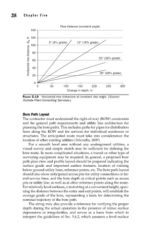
Rise distance (constant angle)
140 5° (9% grade) 10° (18% grade)
120
Horizontal rise distance, S 4 , ft 100 20° (36% grade)
80
60
40
20
0 30° (58% grade)
0 50 100 150 200 250 300
Change in depth, in.
FIGURE 5.19 Horizontal rise distances at constant rise angle. (Source:
Outside Plant Consulting Services.)
Bore Path Layout
The contractor must understand the right-of-way (ROW) constraints
and the general path requirements and utility line architecture for
planning the bore paths. This includes paths for pipes for distribution
lines along the ROW and for services for individual residences or
structures. The anticipated route must take into consideration the
location of other existing utilities (Telcordia, 2007).
For a smooth level area without any underground utilities, a
visual survey and simple sketch may be sufficient for defining the
bore route. In more complicated situations, a transit or other type of
surveying equipment may be required. In general, a proposed bore
path plan view and profile layout should be prepared indicating the
surface grade and important surface features, location of existing
below ground utility lines, reference points, etc. The bore path layout
should also show anticipated access pits for utility connections or lat-
eral service lines, and the bore depth at critical points such as access
pits or utility line, as well as at other reference points along the route.
For relatively level surfaces, a taut string at a convenient height, span-
ning the distance between the entry and exit points, will establish the
average grade of the bore, representing a basis for determining the
nominal trajectory of the bore path.
The string may also provide a reference for verifying the proper
depth during the actual operation in the presence of minor surface
depressions or irregularities, and serves as a basis from which to
interpret the guidelines of Sec. 5.4.2, which assumes a level surface