
Page 245 - Trenchless Technology Piping Installation and Inspection
P. 245
Pr oject Considerations for Horizontal Dir ectional Drilling 209
also helps offset a possible tendency for the pipe to gradually rise
toward the surface due to flotation effects in saturated soil condi-
tions. If a lower depth of cover than that indicated in Fig. 5.15 is nec-
essary, it is recommended that the final borehole size be gradually
enlarged using several (one or more) prereaming passes, prior to the
final pullback of the pipe, accompanied by careful monitoring of the
drilling fluid pressures. In addition to observing the minimum depth
guidelines, excessive depths may not be practical for future mainte-
nance activities on the installed pipes or utility lines.
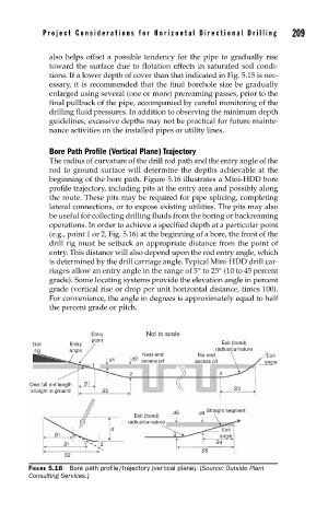
Bore Path Profile (Vertical Plane) Trajectory
The radius of curvature of the drill rod path and the entry angle of the
rod to ground surface will determine the depths achievable at the
beginning of the bore path. Figure 5.16 illustrates a Mini-HDD bore
profile trajectory, including pits at the entry area and possibly along
the route. These pits may be required for pipe splicing, completing
lateral connections, or to expose existing utilities. The pits may also
be useful for collecting drilling fluids from the boring or backreaming
operations. In order to achieve a specified depth at a particular point
(e.g., point 1 or 2, Fig. 5.16) at the beginning of a bore, the front of the
drill rig must be setback an appropriate distance from the point of
entry. This distance will also depend upon the rod entry angle, which
is determined by the drill carriage angle. Typical Mini-HDD drill car-
riages allow an entry angle in the range of 5° to 25° (10 to 45 percent
grade). Some locating systems provide the elevation angle in percent
grade (vertical rise or drop per unit horizontal distance, times 100).
For convenience, the angle in degrees is approximately equal to half
the percent grade or pitch.
Entry Not to scale
point
Drill Entry Exit (bend)
rig angle radius/curvature
Near end Far end Exit
d1 d2 access pit access pit angle
1
2 3
One full rod length S1
straight in ground S2 S3
d3 d4 Straight segment
Exit (bend)
radius/curvature
d Exit
S1 1 3 angle
S1 1 2 S4
S5
S2
FIGURE 5.16 Bore path profi le/trajectory (vertical plane). (Source: Outside Plant
Consulting Services.)