
Page 247 - Trenchless Technology Piping Installation and Inspection
P. 247
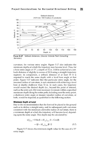
Pr oject Considerations for Horizontal Dir ectional Drilling   211


                                   Setback distance
                            (10 ft rod, 100 ft radius of curvature)
            100
                                                10° (18% grade)
             90
                                     15° (27% grade)
             80
                              20° (36% grade)
             70   S 1
           Setback, ft  60  (S )  (d )
                   2 min
             50
                            2 min
             40
             30
             20
             10
              0
               0    20    40    60   80   100   120   140  160   180
                                     Depth, in.

          FIGURE 5.17  Setback distances. (Source: Outside Plant Consulting
          Services.)

          curvature, for various entry angles. Figure 5.17 also indicates the
          minimum depths at which the trajectory may become level. Thus, for
          a bore entry angle of 15°, a depth of 72 in. will be achieved at a set-
          back distance of slightly in excess of 20 ft using a straight trajectory
          segment. In comparison, a setback distance of at least 35 ft is
          required to reach the same depth with a level bore angle at that
          point. Figure 5.17 indicates that this particular entry angle, for the
          assumed radius of curvature, is not consistent with achieving a level
          bore at depths shallower than 72 in. In such cases, the trajectory
          would exceed the desired depth (i.e., beyond the point of interest,
          such as the entry pit). If it were necessary to remain within a specified
          maximum depth along the entire path, including near the entry point,
          a shallower entry angle or sharper (smaller) radius of curvature, or
          both, would be required, as quantified in the following section.

          Minimum Depth at Level
          Due to the recommendation that the first rod be placed in the ground
          such as to define a straight entry, and its subsequent path curvature
          consistent with the minimum allowable radius of curvature, there is
          a minimum depth at which the trajectory will become level, depend-
          ing upon the entry angle. This depth may be calculated by:

                      (d )   = l Sin β + (R )   (1 – Cos β)
                        2 min         rod min
                                          2
                             ≈ l β + (R )  β /2                 (5.7)
                                     rod min
             Figure 5.17 shows the minimum depth value for the case of a 15°
          entry angle.