
Page 268 - Trenchless Technology Piping Installation and Inspection
P. 268
232 Cha pte r S i x
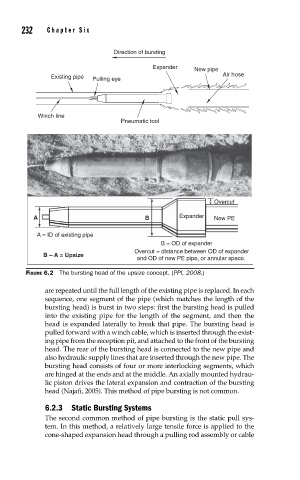
Direction of bursting
Expander New pipe
Air hose
Existing pipe
Pulling eye
Winch line
Pneumatic tool
Overcut
A B Expander New PE
A = ID of existing pipe
B = OD of expander
Overcut = distance between OD of expander
B – A = Upsize
and OD of new PE pipe, or annular space.
FIGURE 6.2 The bursting head of the upsize concept. (PPI, 2008.)
are repeated until the full length of the existing pipe is replaced. In each
sequence, one segment of the pipe (which matches the length of the
bursting head) is burst in two steps: first the bursting head is pulled
into the existing pipe for the length of the segment, and then the
head is expanded laterally to break that pipe. The bursting head is
pulled forward with a winch cable, which is inserted through the exist-
ing pipe from the reception pit, and attached to the front of the bursting
head. The rear of the bursting head is connected to the new pipe and
also hydraulic supply lines that are inserted through the new pipe. The
bursting head consists of four or more interlocking segments, which
are hinged at the ends and at the middle. An axially mounted hydrau-
lic piston drives the lateral expansion and contraction of the bursting
head (Najafi, 2005). This method of pipe bursting is not common.
6.2.3 Static Bursting Systems
The second common method of pipe bursting is the static pull sys-
tem. In this method, a relatively large tensile force is applied to the
cone-shaped expansion head through a pulling rod assembly or cable