
Page 289 - Trenchless Technology Piping Installation and Inspection
P. 289
Pr oject Considerations for Pipe Replacement Methods 253
(a) (b)
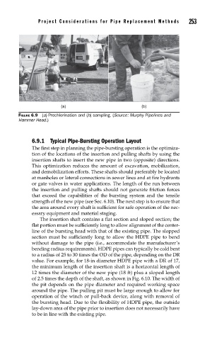
FIGURE 6.9 (a) Prechlorination and (b) sampling. (Source: Murphy Pipelines and
Hammer Head.)
6.9.1 Typical Pipe-Bursting Operation Layout
The first step in planning the pipe-bursting operation is the optimiza-
tion of the locations of the insertion and pulling shafts by using the
insertion shafts to insert the new pipe in two (opposite) directions.
This optimization reduces the amount of excavation, mobilization,
and demobilization efforts. These shafts should preferably be located
at manholes or lateral connections in sewer lines and at fire hydrants
or gate valves in water applications. The length of the run between
the insertion and pulling shafts should not generate friction forces
that exceed the capabilities of the bursting system and the tensile
strength of the new pipe (see Sec. 6.10). The next step is to ensure that
the area around every shaft is sufficient for safe operation of the nec-
essary equipment and material staging.
The insertion shaft contains a flat section and sloped section; the
flat portion must be sufficiently long to allow alignment of the center-
line of the bursting head with that of the existing pipe. The slopped
section must be sufficiently long to allow the HDPE pipe to bend
without damage to the pipe (i.e., accommodate the manufacturer’s
bending radius requirements). HDPE pipes can typically be cold bent
to a radius of 25 to 30 times the OD of the pipe, depending on the DR
value. For example, for 18-in diameter HDPE pipe with a DR of 17,
the minimum length of the insertion shaft is a horizontal length of
12 times the diameter of the new pipe (18 ft) plus a sloped length
of 2.5 times the depth of the shaft, as shown in Fig. 6.10. The width of
the pit depends on the pipe diameter and required working space
around the pipe. The pulling pit must be large enough to allow for
operation of the winch or pull-back device, along with removal of
the bursting head. Due to the flexibility of HDPE pipe, the outside
lay-down area of the pipe prior to insertion does not necessarily have
to be in line with the existing pipe.