
Page 290 - Trenchless Technology Piping Installation and Inspection
P. 290
254 Cha pte r S i x
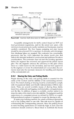
Direction of insertion
Polyethylene pipe
2.5 × D 12 × d
Winch assembly
D
Existing pipe with crown D = Depth to invert
removed to spring line
d = Diameter of liner pipe
FIGURE 6.10 Insertion shaft dimensions for HDPE pipe with DR 17.
Acceptable arrangements for traffic control (based on DOT and
local government regulations, and for the joined new pipe), with
minimum inconvenience to nearby residents and businesses, must be
carefully considered. The flow bypass pumping and pipe layout
should be also planned. If it is necessary to dewater, safe and proper
flow discharge plans are required. The contractor has, presumably,
previously (see Sec. 6.8.9) submitted the jobsite layout plan that
reflects the intended method of construction and addresses the above
considerations. The contractor does not start the bursting operation
before the engineer has reviewed and approved the jobsite layout
plan. The site inspector enforces the adherence to this plan unless
there is a valid reason for the deviation, and has been approved
by the engineer or owner. If contaminated soil is excavated, the con-
tractor must take the necessary measures for handling and disposal
of the contaminated soil.
6.9.2 Shoring the Entry and Pulling Shafts
Proper shoring of the entry and pulling shafts is essential for the
safety of the workers and the stability of the surrounding environ-
ment. The trench shoring or bracing must be constructed to comply
with Occupational Safety and Health Administration (OSHA) stan-
dards. There are several available means of shoring these shafts:
trench box, solder pile and lagging, steel sheet piles, corrugated pipes,
and the like. In addition, if space is available, another option is to
slope the sides of the shaft to provide stability. The judgment and the
supervision of a competent person (as defined by OSHA) or a quali-
fied geotechnical engineer is required to ensure the shoring is safe.
In static pipe bursting method, the winch will thrust against the
wall of the pulling shaft on one side. This side must be capable of
withstanding the corresponding pressure. Since the pulling forces
in static bursting applications are relatively high, in such cases the
contractor should construct a thrust block to distribute the forces