
Page 47 - Trenchless Technology Piping Installation and Inspection
P. 47
20 Cha pte r O n e
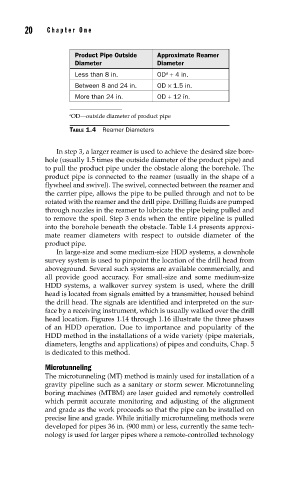
Product Pipe Outside Approximate Reamer
Diameter Diameter
Less than 8 in. OD + 4 in.
a
Between 8 and 24 in. OD × 1.5 in.
More than 24 in. OD + 12 in.
a OD—outside diameter of product pipe
TABLE 1.4 Reamer Diameters
In step 3, a larger reamer is used to achieve the desired size bore-
hole (usually 1.5 times the outside diameter of the product pipe) and
to pull the product pipe under the obstacle along the borehole. The
product pipe is connected to the reamer (usually in the shape of a
flywheel and swivel). The swivel, connected between the reamer and
the carrier pipe, allows the pipe to be pulled through and not to be
rotated with the reamer and the drill pipe. Drilling fluids are pumped
through nozzles in the reamer to lubricate the pipe being pulled and
to remove the spoil. Step 3 ends when the entire pipeline is pulled
into the borehole beneath the obstacle. Table 1.4 presents approxi-
mate reamer diameters with respect to outside diameter of the
product pipe.
In large-size and some medium-size HDD systems, a downhole
survey system is used to pinpoint the location of the drill head from
aboveground. Several such systems are available commercially, and
all provide good accuracy. For small-size and some medium-size
HDD systems, a walkover survey system is used, where the drill
head is located from signals emitted by a transmitter, housed behind
the drill head. The signals are identified and interpreted on the sur-
face by a receiving instrument, which is usually walked over the drill
head location. Figures 1.14 through 1.16 illustrate the three phases
of an HDD operation. Due to importance and popularity of the
HDD method in the installations of a wide variety (pipe materials,
diameters, lengths and applications) of pipes and conduits, Chap. 5
is dedicated to this method.
Microtunneling
The microtunneling (MT) method is mainly used for installation of a
gravity pipeline such as a sanitary or storm sewer. Microtunneling
boring machines (MTBM) are laser guided and remotely controlled
which permit accurate monitoring and adjusting of the alignment
and grade as the work proceeds so that the pipe can be installed on
precise line and grade. While initially microtunneling methods were
developed for pipes 36 in. (900 mm) or less, currently the same tech-
nology is used for larger pipes where a remote-controlled technology