
Page 49 - Trenchless Technology Piping Installation and Inspection
P. 49
22 Cha pte r O n e
is required. These methods require a drive shaft for jacking the pipe
and an exit shaft for retrieving the MTBM. The microtunneling
method include main components of:
• Remote controlled: The MTBM is remotely operated from a
control panel, normally located on the surface. This method
excavates and removes the soil and installs the pipe.
• Laser guided: The guidance system usually is a laser beam pro-
jected onto a target in the MTBM, capable of installing gravity
sewers or other types of pipeline which require accurate line
and grade.
• Jacking system: The process of constructing a pipeline by con-
secutively pushing the MTBM through the ground using a
jacking system.
• Face support: Continuous pressure is provided to the face of
the excavation to balance groundwater and earth pressure.
The microtunneling method installs pipe with an accuracy of
±1 in. in both the horizontal and vertical alignments. The most com-
mon spoil-removal system for microtunneling is a slurry transporta-
tion system. With proper planning, soil identification, and MTBM
selection, microtunneling methods are applicable to many types of
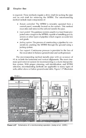
soils, either above or below groundwater table. Figure 1.17 illustrates
Soil skip or
separation plant
Slurry Tanks Charging
slurry
pump Operation Power pack
board
Slurry discharge Slurry discharge
Flow Flow
Magnetic
flow
meter Main jacking
unit
Break- Discharge
out ring slurry
Cutterhead Laser target seal pump Laser
Shield TV camera
FIGURE 1.17 Schematics of a microtunneling operation. (Iseley et al., 1999.)