
Page 112 - Tribology in Machine Design
P. 112
98 Tribology in machine design
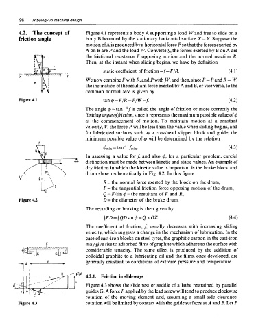
4.2. The concept of Figure 4.1 represents a body A supporting a load W and free to slide on a
friction angle body B bounded by the stationary horizontal surface X—Y. Suppose the
motion of A is produced by a horizontal force P so that the forces exerted by
A on B are P and the load W. Conversely, the forces exerted by B on A are
the frictional resistance F opposing motion and the normal reaction R.
Then, at the instant when sliding begins, we have by definition
We now combine F with /?, and P with, W, and then, since F = P and R = W,
the inclination of the resultant force exerted by A and B, or vice versa, to the
common normal NN is given by
Figure 4.1
The angle </> = tan l fi s called the angle of friction or more correctly the
limiting angle of friction, since it represents the maximum possible value of 4>
at the commencement of motion. To maintain motion at a constant
velocity, K, the force P will be less than the value when sliding begins, and
for lubricated surfaces such as a crosshead slipper block and guide, the
minimum possible value of (/> will be determined by the relation
In assessing a value for/, and also (f>, for a particular problem, careful
distinction must be made between kinetic and static values. An example of
dry friction in which the kinetic value is important is the brake block and
drum shown schematically in Fig. 4.2. In this figure
R = the normal force exerted by the block on the drum,
F = the tangential friction force opposing motion of the drum,
Q = F/sin(j)=the resultant of F and R,
Figure 4.2 D = the diameter of the brake drum.
The retarding or braking is then given by
The coefficient of friction, /, usually decreases with increasing sliding
velocity, which suggests a change in the mechanism of lubrication. In the
case of cast-iron blocks on steel tyres, the graphitic carbon in the cast-iron
may give rise to adsorbed films of graphite which adhere to the surface with
considerable tenacity. The same effect is produced by the addition of
colloidal graphite to a lubricating oil and the films, once developed, are
generally resistant to conditions of extreme pressure and temperature.
4.2.1. Friction in slideways
Figure 4.3 shows the slide rest or saddle of a lathe restrained by parallel
guides G. A force F applied by the lead screw will tend to produce clockwise
rotation of the moving element and, assuming a small side clearance,
Figure 4.3 rotation will be limited by contact with the guide surfaces at A and B. Let P