
Page 116 - Tribology in Machine Design
P. 116
102 Tribology in machine design
Figure 4.6
as the wedge moves forward under the action of a force P, the reaction R 3 at
S must pass above 0, the point of intersection of RI and W. Hence, tilting
will tend to occur, and the guide reactions will be concentrated at S and X as
shown in Fig. 4.6.
The force diagram for the system is readily drawn. Thus hgf is the triangle
offerees for the wedge (the weight of the wedge is neglected). For the block
B, oh represents the weight W; /i/the reaction R^ at £; and, since the
resultant of R$ and R 4 must be equal and opposite to the resultant of/?! and
W, of must be parallel to OF, where F is the point of intersection of R 3 and
R 4. The diagram ohgfk can now be completed.
Numerical example
4
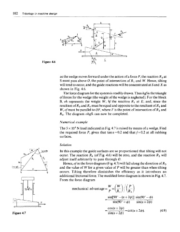
The 5 x 10 N load indicated in Fig. 4.7 is raised by means of a wedge. Find
the required force P, given that tan a =0.2 and that/= 0.2 at all rubbing
surfaces.
Solution
In this example the guide surfaces are so proportioned that tilting will not
occur. The reaction R 4 (of Fig. 4.6) will be zero, and the reaction R 3 will
adjust itself arbitrarily to pass through 0.
Hence, of in the force diagram (Fig. 4.7) will fall along the direction of R 3
and the value of W for a given value of P will be greater than when tilting
occurs. Tilting therefore diminishes the efficiency as it introduces an
additional frictional force. The modified force diagram is shown in Fig. 4.7.
From the force diagram
Figure 4.7