
Page 121 - Tribology in Machine Design
P. 121
Friction, lubrication and wear in lower kinematic pairs 107
then, reducing the frictional effects to radius r
f
the virtual coefficient of friction for the nut = tan <f> 2 =/—
r
d
the virtual coefficient of friction for the key=tan</> 3 =/-.
The system is now analogous to the problem of the wedge as in Section 4.2.
l
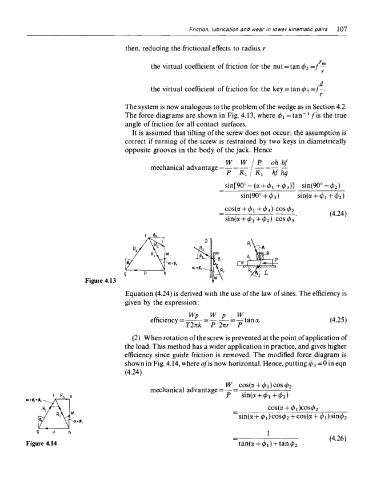
The force diagrams are shown in Fig. 4.13, where </>! = tan~ fi s the true
angle of friction for all contact surfaces.
It is assumed that tilting of the screw does not occur; the assumption is
correct if turning of the screw is restrained by two keys in diametrically
opposite grooves in the body of the jack. Hence
Figure 4.13
Equation (4.24) is derived with the use of the law of sines. The efficiency is
given by the expression:
(2) When rotation of the screw is prevented at the point of application of
the load. This method has a wider application in practice, and gives higher
efficiency since guide friction is removed. The modified force diagram is
shown in Fig. 4.14, where o/is now horizontal. Hence, putting </> 3 =0 in eqn
(4.24)
Figure 4.14