
Page 119 - Tribology in Machine Design
P. 119
Friction, lubrication and wear in lower kinematic pairs 105
the fact that when a>0 the machine will not sustain the load when the
effort is removed. Thus, referring to the inclined plane, Fig. 4.9, if the motion
is reversed the reaction R l will lie on the opposite side of the normal ON in
such a manner as to oppose motion. Hence, reversing the sign of 0 in eqn
(4.14)
and if a > <f> this result gives the value of P which will just prevent downward
Figure 4.10
motion. Alternatively, if a < </>, the force P becomes negative and is that
value which will just produce downward motion. In the latter case the
system is said to be self-locking or self-sustaining and is shown in Fig. 4.10.
When a = </> the system is just self-sustaining. Thus, if a = (f) = 6°, cor-
responding to the value of/=0.1, then when the load is being raised
and
On the other hand, for the value a =42°, corresponding to the maximum
efficiency given above
and the mechanical advantage is reduced in the ratio 4.75:0.9 = 5.23:1.
In general, the following is approximately true: a machine will sustain its
load, if the effort is removed, when its efficiency, working direct, is less than
50 per cent.
4.3.1. Application of a threaded screw in a jack
The screw jack is a simple example of the use of the square threaded screw
and may operate by either:
(i) rotating the screw when the nut is fixed; or
(ii) rotating the nut and preventing rotation of the screw.
Two cases shall be considered.
Case (i) The nut is fixed
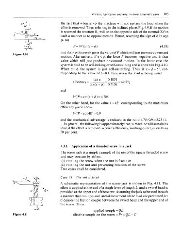
A schematic representation of the screw-jack is shown in Fig. 4.11. The
effort is applied at the end of a single lever of length L, and a swivel head is
provided at the upper end of the screw. Assuming the jack to be used in such
a manner that rotation and lateral movement of the load are prevented, let
C denote the friction couple between the swivel head and the upper end of
the screw. Then
Figure 4.11