
Page 115 - Tribology in Machine Design
P. 115
Friction, lubrication and wear in lower kinematic pairs 101
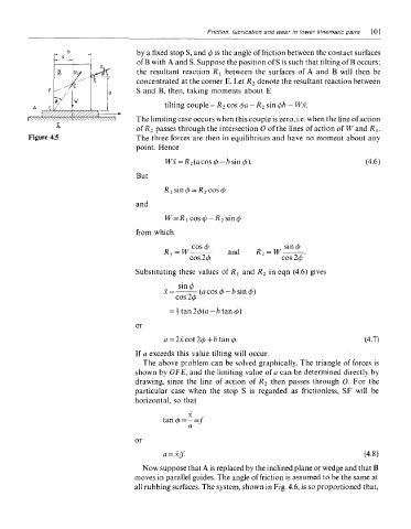
by a fixed stop S, and 4> is the angle of friction between the contact surfaces
of B with A and S. Suppose the position of S is such that tilting of B occurs;
the resultant reaction R± between the surfaces of A and B will then be
concentrated at the corner E. Let R 2 denote the resultant reaction between
S and B, then, taking moments about E
The limiting case occurs when this couple is zero, i.e. when the line of action
of ,R 2 passes through the intersection 0 of the lines of action of Wand R^.
Figure 4.5 The three forces are then in equilibrium and have no moment about any
point. Hence
But
and
from which
Substituting these values of/?! and R 2 in eqn (4.6) gives
If a exceeds this value tilting will occur.
The above problem can be solved graphically. The triangle of forces is
shown by OFE, and the limiting value of a can be determined directly by
drawing, since the line of action of R 2 then passes through O. For the
particular case when the stop S is regarded as frictionless, SF will be
horizontal, so that
Now suppose that A is replaced by the inclined plane or wedge and that B
moves in parallel guides. The angle of friction is assumed to be the same at
all rubbing surfaces. The system, shown in Fig. 4.6, is so proportioned that,