
Page 165 - Tribology in Machine Design
P. 165
Friction, lubrication and wear in lower kinematic pairs 151
and front axle bearings. When running at a constant speed these friction
torques will exert a constant tractive resistance as given by eqns (4.157) and
(4.158) when a = 0,i.e.F 1 +F 2 = (L 1 +L 2 )/a. This tractive resistance must be
deducted from the tractive effort to obtain the effective force for the
calculation of acceleration. It must be remembered that there is no loss of
energy in a pure rolling action, provided that wheel spin or skidding does
not occur. In the ideal case, when friction in a bearing is neglected, so that
L l=L 2=Q and F!=F 2 =0, the vehicle would run freely without
retardation.
4.14. Pneumatic tyres A pneumatic tyre fitted on the wheel can be modelled as an elastic body in
rolling contact with the ground. As such, it is subjected to creep and micro-
slip. Tangential force and twisting arising from the lateral creep and usually
referred to as the cornering force and the self-aligning torque, play, in fact, a
significant role in the steering process of a vehicle. For obvious reasons, the
analysis which is possible for solid isotropic bodies cannot be done in the
case of a tyre. Simple, one-dimensional models, however, have been
proposed to describe the experimentally observed behaviour. An ap-
proximately elliptically shaped contact area is created when a toroidal
membrane with internal pressure is pressed against a rigid plane surface.
The size of the contact area can be compared with that created by the
intersection of the plane with the undeformed surface of the toroid, at such a
location as to give an area which is sufficient to support the applied load by
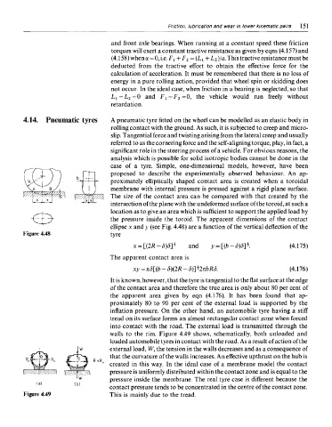
the pressure inside the toroid. The apparent dimensions of the contact
ellipse x and y (see Fig. 4.48) are a function of the vertical deflection of the
Figure 4.48 tyre
The apparent contact area is
It is known, however, that the tyre is tangential to the flat surface at the edge
of the contact area and therefore the true area is only about 80 per cent of
the apparent area given by eqn (4.176). It has been found that ap-
proximately 80 to 90 per cent of the external load is supported by the
inflation pressure. On the other hand, an automobile tyre having a stiff
tread on its surface forms an almost rectangular contact zone when forced
into contact with the road. The external load is transmitted through the
walls to the rim. Figure 4.49 shows, schematically, both unloaded and
loaded automobile tyres in contact with the road. As a result of action of the
external load, W, the tension in the walls decreases and as a consequence of
that the curvature of the walls increases. An effective upthrust on the hub is
created in this way. In the ideal case of a membrane model the contact
pressure is uniformly distributed within the contact zone and is equal to the
pressure inside the membrane. The real tyre case is different because the
contact pressure tends to be concentrated in the centre of the contact zone.
Figure 4.49 This is mainly due to the tread.