
Page 170 - Tribology in Machine Design
P. 170
156 Tribology in machine design
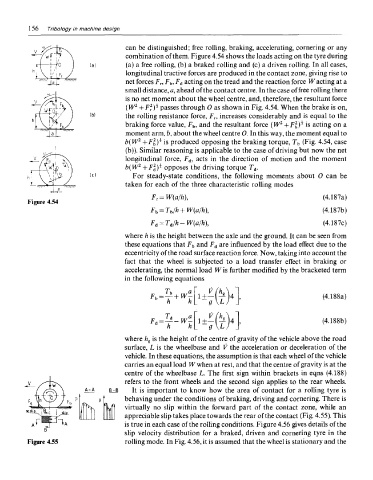
can be distinguished; free rolling, braking, accelerating, cornering or any
combination of them. Figure 4.54 shows the loads acting on the tyre during
(a) a free rolling, (b) a braked rolling and (c) a driven rolling. In all cases,
longitudinal tractive forces are produced in the contact zone, giving rise to
net forces F r, F b, F d acting on the tread and the reaction force W acting at a
small distance, a, ahead of the contact centre. In the case of free rolling there
is no net moment about the wheel centre, and, therefore, the resultant force
2
2
(W + F .)* passes through 0 as shown in Fig. 4.54. When the brake is on,
the rolling resistance force, F r, increases considerably and is equal to the
2
braking force value, F b, and the resultant force (W +Fffi is acting on a
moment arm, b, about the wheel centre 0. In this way, the moment equal to
2
b(W + F b )* is produced opposing the braking torque, T b (Fig. 4.54, case
(b)). Similar reasoning is applicable to the case of driving but now the net
longitudinal force, F d, acts in the direction of motion and the moment
2
b(W +Fffi opposes the driving torque T d.
For steady-state conditions, the following moments about 0 can be
taken for each of the three characteristic rolling modes
Figure 4.54
where h is the height between the axle and the ground. It can be seen from
these equations that F b and F d are influenced by the load effect due to the
eccentricity of the road surface reaction force. Now, taking into account the
fact that the wheel is subjected to a load transfer effect in braking or
accelerating, the normal load W is further modified by the bracketed term
in the following equations
where h s is the height of the centre of gravity of the vehicle above the road
surface, L is the wheelbase and V the acceleration or deceleration of the
vehicle. In these equations, the assumption is that each wheel of the vehicle
carries an equal load W when at rest, and that the centre of gravity is at the
centre of the wheelbase L. The first sign within brackets in eqns (4.188)
refers to the front wheels and the second sign applies to the rear wheels.
It is important to know how the area of contact for a rolling tyre is
behaving under the conditions of braking, driving and cornering. There is
virtually no slip within the forward part of the contact zone, while an
appreciable slip takes place towards the rear of the contact (Fig. 4.55). This
is true in each case of the rolling conditions. Figure 4.56 gives details of the
slip velocity distribution for a braked, driven and cornering tyre in the
Figure 4.55 rolling mode. In Fig. 4.56, it is assumed that the wheel is stationary and the