
Page 172 - Tribology in Machine Design
P. 172
158 Tribology in machine design
The tread elements must force their way through the water film in order to
establish physical contact with the road surface asperities (Fig. 4.57, case
(b)). Throughout the entire contact length the normal load on the tread
elements is due to the inflation pressure of the tyre. In the region BC of the
contact length, a draping of the tread about the highest asperities on the
road surface takes place. The extent and rate of penetration of the tread by
the road surface asperities is mainly determined by the properties of the
rubber, such as hardness, hysteresis losses and resilience. The process of
draping is over when an equilibrium in vertical direction is established,
point C in Fig. 4.57.
The clear inference is that under wet conditions the real contact between
the tyre and the road surface is taking place in the region CD (Fig. 4.57). It is
then quite obvious that by minimizing the length AB, by a suitable choice of
tread pattern, the length CD used for traction developing is increased,
provided that the region BC remains unaffected and velocity V is
unchanged. The increase in rolling velocity invariably causes growth of the
squeeze-film region AB, to such an extent that it occupies almost the whole
length of the contact zone AD. This leads to very low traction forces. The
speed at which this happens is referred to as the viscous hydroplaning limit
and is mainly defined by the ability of the front part of the contact zone to
squeeze the water film out. At this critical speed the hydrodynamic pressure
developed within the contact zone is quite large but is not sufficient to
support the normal load, W, on the wheel. There is a second, much higher
speed, at which the hydrodynamic pressure is equal to the load on the wheel
and is called the dynamic hydroplaning limit. The dynamic hydroplaning
Figure 4.58
limit is reached only in a few practical situations, for instance, during the
landing of an aeroplane. More commonplace is the viscous hydroplaning
limit which represents a critical rolling velocity for all road vehicles when
the region AB takes a significant part of the contact zone AD.
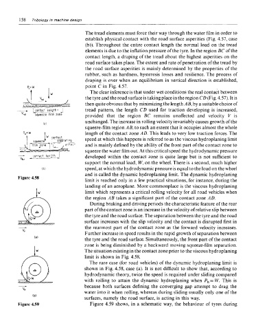
During braking and driving periods the characteristic feature of the rear
part of the contact zone is an increase in the velocity of relative slip between
the tyre and the road surface. The separation between the tyre and the road
surface increases with the slip velocity and the contact is disrupted first in
the rearmost part of the contact zone as the forward velocity increases.
Further increase in speed results in the rapid growth of separation between
the tyre and the road surface. Simultaneously, the front part of the contact
zone is being diminished by a backward moving squeeze-film separation.
The situation existing in the contact zone prior to the viscous hydroplaning
limit is shown in Fig. 4.58.
The rare case (for road vehicles) of the dynamic hydroplaning limit is
shown in Fig. 4.58, case (a). It is not difficult to show that, according to
hydrodynamic theory, twice the speed is required under sliding compared
with rolling to attain the dynamic hydroplaning when P h = W. This is
because both surfaces defining the converging gap attempt to drag the
water into it when rolling, whereas during sliding usually only one of the
surfaces, namely the road surface, is acting in this way.
Figure 4.59 Figure 4.59 shows, in a schematic way, the behaviour of tyres during