
Page 171 - Tribology in Machine Design
P. 171
Friction, lubrication and wear in lower kinematic pairs 157
Figure 4.56
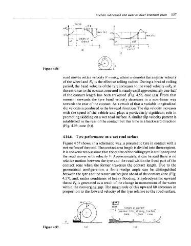
road moves with a velocity V = o)R 0, where co denotes the angular velocity
of the wheel and R 0 is the effective rolling radius. During a braked rolling
period, the band velocity of the tyre increases to the road velocity a)R 0 at
the entrance to the contact zone and is steady until approximately one-half
of the contact length has been traversed (Fig. 4.56, case (a)). From that
moment onwards the tyre band velocity decreases in a non-linear way
towards the rear of the contact. As a result of that a variable longitudinal
slip velocity is produced in the forward direction. The slip velocity increases
with the speed of the vehicle and plays a particularly significant role in
promoting skidding on a wet road surface. A similar slip velocity pattern is
established in the rear of the contact but this time in a backward direction
(Fig. 4.56, case (b)).
4.14.6. Tyre performance on a wet road surface
Figure 4.57 shows, in a schematic way, a pneumatic tyre in contact with a
wet surface of the road. The contact area length is divided into three regions.
It is convenient to assume that the centre of the rolling tyre is stationary and
the road moves with velocity V. Approximately, it can be said there is no
relative motion between the tyre and the road within the front part of the
contact zone when the former traverses the contact length. Due to the
geometrical configuration, a finite wedge angle can be distinguished
between the tyre and the water surface just ahead of the contact zone (Fig.
4.57), and, under conditions of heavy flooding, a hydrodynamic upward
thrust P h is generated as a result of the change in momentum of the water
within the converging gap. The magnitude of this upward lift increases in
proportion to the forward velocity of the tyre relative to the road surface.
Figure 4.57