
Page 177 - Tribology in Machine Design
P. 177
Friction, lubrication and wear in lower kinematic pairs 163
following formula:
Assuming a value of 0.1 Pas for viscosity, /*, and /i = 5xl O 7 m, the
relationship between the flow and the pressure gradient becomes
Thus, assuming a seal face of size 1 cm measured in the direction of flow, a
9
pressure difference of 20MPa, and dp/dx = 2x 10 , the flow would be
l
Figure 4.64 4.34 x 10" m s~ . This would hardly keep pace with evaporation and it
12
3
may be accepted that viscous resistance to flow, whilst it can never prevent
leakage, may reduce it to a negligible quantity. In practice, surfaces will not
be flat and parallel as assumed in the foregoing treatment, and in fact there
will be a more complicated flow path as depicted schematically in Fig. 4.64.
Some substances, such as lubricating greases may possess yield values
which will prevent leakage until a certain pressure is exceeded and some
microscopic geometrical feature of the surfaces may cause an inward
pumping action to counteract the effect of applied pressure. Under
favourable circumstances hydrodynamic pressure may be generated to
oppose the flow due to the applied pressure.
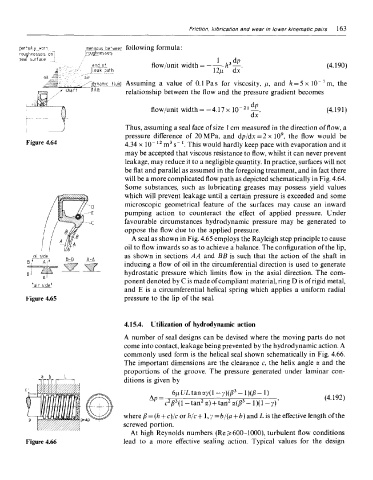
A seal as shown in Fig. 4.65 employs the Rayleigh step principle to cause
oil to flow inwards so as to achieve a balance. The configuration of the lip,
as shown in sections AA and BB is such that the action of the shaft in
inducing a flow of oil in the circumferential direction is used to generate
hydrostatic pressure which limits flow in the axial direction. The com-
ponent denoted by C is made of compliant material, ring D is of rigid metal,
and E is a circumferential helical spring which applies a uniform radial
Figure 4.65 pressure to the lip of the seal.
4.15.4. Utilization of hydrodynamic action
A number of seal designs can be devised where the moving parts do not
come into contact, leakage being prevented by the hydrodynamic action. A
commonly used form is the helical seal shown schematically in Fig. 4.66.
The important dimensions are the clearance c, the helix angle a and the
proportions of the groove. The pressure generated under laminar con-
ditions is given by
where fi = (h + c)/c orh/c+l,y= b/(a + b) and L is the effective length of the
screwed portion.
At high Reynolds numbers (Re Js 600-1000), turbulent flow conditions
Figure 4.66 lead to a more effective sealing action. Typical values for the design