
Page 221 - Tribology in Machine Design
P. 221
206 Tribology in machine design
subsynchronous vibration at high speeds. Accurate manufacture of these
bearings is not always easy to obtain. A key parameter used in describing
these bearings is the fraction of converging pad to full pad length. Ratio a is
called the offset factor and is given by
a = converging pad length/pad arc length.
An elliptical bearing, as shown in Fig. 5.25, indicates that the two pad
centres of curvature are moved along the y-axis. This creates a pad which
has each film thickness and which is one-half converging and one-half
diverging (if the shaft were centred) corresponding to an offset factor
a =0.5. Another offset half-bearing shown in Fig. 5.25 consists of a two-
axial groove bearing which is split by moving the top half horizontally. This
results in low vertical stiffness. Basically it is no more difficult to make than
the axial groove bearing. Generally, the vibration characteristics of this
bearing are such as to avoid the previously mentioned oil whirl which can
drive the machine unstable. The offset half-bearing has a purely converging
pad with pad arc length 160° and the point opposite the centre of curvature
at 180°. Both the three-lobe and four-lobe bearings shown in Fig. 5.25 have
an offset factor of a =0.5.
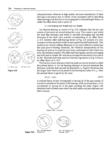
The fraction of pad clearance which the pads are moved inwards is called
the preload factor, m. Let the bearing clearance at the pad minimum film
thickness (with the shaft centred) be denoted by c b. Figure 5.26 shows that
Figure 5.25 the largest shaft which can be placed in the bearing has radius R + c b. Then
the preload factor is given by the ratio
A preload factor of zero corresponds to having all of the pad centres of
curvature coincide at the centre of the bearing, while a preload factor of 1.0
corresponds to having all of the pads touching the shaft. Figure 5.26
illustrates both of these cases where the shaft radius and pad clearance are
held constant.
Figure 5.26