
Page 222 - Tribology in Machine Design
P. 222
Sliding-element bearings 207
dam
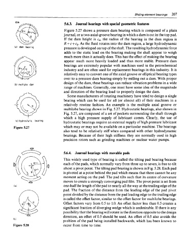
5.6.3. Journal bearings with special geometric features
Figure 5.27 shows a pressure dam bearing which is composed of a plain
journal, or a two-axial-groove bearing in which a dam is cut in the top pad.
If the dam height is c d, the radius of the bearing in the dam region is
R + c + c d. As the fluid rotates into the dam region, a large hydrodynamic
pressure is developed on top of the shaft. The resulting hydrodynamic force
adds to the static load on the bearing making the shaft appear to weigh
much more than it actually does. This has the effect of making the bearing
appear much more heavily loaded and thus more stable. Pressure dam
bearings are extremely popular with machines used in the petrochemical
industry and are often used for replacement bearings in this industry. It is
relatively easy to convert one of the axial groove or elliptical bearing types
over to a pressure dam bearing simply by milling out a dam. With proper
design of the dam, these bearings can reduce vibration problems in a wide
range of machines. Generally, one must have some idea of the magnitude
and direction of the bearing load to properly design the dam.
Some manufacturers of rotating machinery have tried to design a single
bearing which can be used for all (or almost all) of their machines in a
relatively routine fashion. An example is the multiple axial groove or
multilobe bearing shown in Fig. 5.27. Hydrostatic bearings, also shown in
Fig. 5.27, are composed of a set of pockets surrounding the shaft through
which a high pressure supply of lubricant comes. Clearly, the use of
hydrostatic bearings require an external supply of high pressure lubricant
which may or may not be available on a particular machine. The bearings
also tend to be relatively stiff when compared with other hydrodynamic
bearings. Because of their high stiffness they are normally used in high
precision rotors such as grinding machines or nuclear water pumps.
5.6.4. Journal bearings with movable pads
This widely used type of bearing is called the tilting pad bearing because
each of the pads, which normally vary from three up to seven, is free to tilt
about a pivot point. The tilting pad bearing is shown in Fig. 5.28. Each pad
is pivoted at a point behind the pad which means that there cannot be any
moment acting on the pad. The pad tilts such that its centre of curvature
moves to create a strongly converging pad film. The pivot point is set from
one-half the length of the pad to nearly all the way at the trailing edge of the
pad. The fraction of the distance from the leading edge of the pad pivot
point divided by the distance from the pad leading edge to the trailing edge
is called the offset factor, similar to the offset factor for multilobe bearings.
Offset factors vary from 0.5 to 1.0. An offset factor less than 0.5 creates a
significant fraction of diverging wedge which is undesirable. If there is any
possibility that the bearing will rotate in the direction opposite to the design
direction, an offset of 0.5 should be used. An offset of 0.5 also avoids the
problem of the pad being installed backwards, which has been known to
Figure 5.28 occur from time to time.