
Page 45 - Tribology in Machine Design
P. 45
32 Tribology in machine design
greatly accelerates fatigue, for example, by hydrogen embrittlement of iron,
so that V fc will tend to be large and positive. On the other hand, adhesion
and fatigue rarely, if ever, coexist, and this is presumably because adhesive
wear destroys the microcracks from which fatigue propagates. Hence, the
wear volume F fa due to the interaction between fatigue and adhesion will
always be zero. Since adhesion and corrosion are dimensionally similar, it
may be hoped that K ac and K fac will prove to be negligible. If this is so, only
F fc needs to be evaluated. By assuming that the lubricant is not corrosive
and that the environment is not excessively humid, it is possible to simplify
eqn (2.50) further, and to reduce it to the form
According to the model presented here adhesive wear takes place on the
metal-metal contact area, A m, whereas fatigue wear should take place on
the remaining real area of contact, that is, A r — A m. Repeated stressing
through the thin adsorbed lubricant film existing on these micro-areas of
contact would be expected to produce fatigue wear.
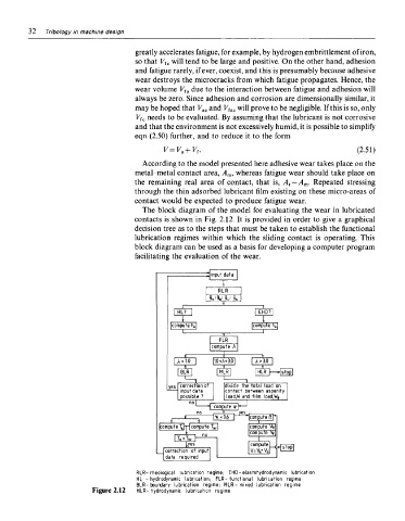
The block diagram of the model for evaluating the wear in lubricated
contacts is shown in Fig. 2.12. It is provided in order to give a graphical
decision tree as to the steps that must be taken to establish the functional
lubrication regimes within which the sliding contact is operating. This
block diagram can be used as a basis for developing a computer program
facilitating the evaluation of the wear.
RLR-Theological lubrication regime; EHD-elastohydrodynamic lubrication
HL - hydrodynamic lubrication; FLR-functional lubrication regime
BLR-boundary lubrication regime; MLR- mixed lubrication regime
Figure 2.12 HLR-hydrodynamic lubrication regime