
Page 54 - Tribology in Machine Design
P. 54
Basic principles of tribology 41
width of the contact region taken in a plane parallel to the direction of
motion and r max is the maximum shear stress occurring in the vicinity of the
contact region.
For non-zero wear it is assumed that a certain portion of the energy
expanded in sliding and used to create wear debris is proportional to T max5.
Integration of eqn (2.89) results in an expression which shows how wear
progresses as the number of operations of a mechanism increases. The
manner in which such an expression is obtained for the pin-on-disc
configuration is illustrated by a numerical example.
The procedure for calculating non-zero wear is somewhat complicated
because there is no simple algebraic expression available for relating
lifetime to design parameters for the general case. The development of the
necessary expressions for the determination of suitable combinations of
design parameters is a step-like procedure. The first step involves integ-
ration of the particular form of the differential equation of which eqn (2.89)
is the general form. This step results in a relationship between Q and the
allowable total number L of sliding passes and usually involves parameters
which depend on load, geometry and material properties. The second step is
the determination of the dependence of the parameters on these properties.
From these steps, expressions are derived to determine whether a given set
of design parameters is satisfactory, and the values that certain parameters
must assume so that the wear will be acceptable.
2.11.7. Numerical example
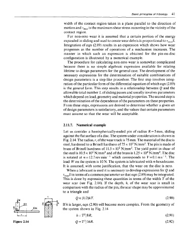
Let us consider a hemispherically-ended pin of radius R = 5 mm, sliding
against the flat surface of a disc. The system under consideration is shown in
Fig. 2.14. The radius, r, of the wear track is 75 mm. The material of the disc is
2
2
steel, hardened to a Brinell hardness of 75 x 10 N/mm . The pin is made of
2
2
brass of Brinell hardness of 11.5 x 10 N/mm . The yield point in shear of
2
2
2
2
the steel is 10.5 x 10 N/mm and of the brass is 1.25 x 10 N/mm . The disc
1
1
is rotated at n = 12.7revmin~ which corresponds to F=0.1ms~ . The
load Won the system is ION. The system is lubricated with n-hexadecane.
It is assumed, with some justification, that the wear on the disc is zero.
When a lubricant is used it is necessary to develop expressions for Q and
T maxS in terms of a common parameter so that eqn (2.89) may be integrated.
This is done by expressing these quantities in terms of the width T of the
wear scar (see Fig. 2.14). If the depth, h, of the wear scar is small in
comparison with the radius of the pin, the scar shape may be approximated
to a triangle and
If h is larger, eqn (2.90) will become more complex. From the geometry of
the system shown in Fig. 2.14
Figure 2.14