
Page 80 - Tribology in Machine Design
P. 80
Elements of contact mechanics 67
3.3. Contact between When two elastic bodies with convex surfaces, or one convex and one plane
two elastic bodies in the surface, or one convex and one concave surface, are brought together in
form of spheres point or line contact and then loaded, local deformation will occur, and the
point or line will enlarge into a surface of contact. In general, its area is
bounded by an ellipse, which becomes a circle when the contacting bodies
are spheres, and a narrow rectangle when they are cylinders with parallel
axes. These cases differ from those of the preceding section in that there are
two elastic members, and the pressure between them must be determined
from their geometry and elastic properties.
The solutions for deformation, area of contact, pressure distribution and
stresses at the initial point of contact were made by Hertz. They are
presented in ESDU 78035 in a form suitable for engineering application.
The maximum compressive stress, acting normal to the surface is equal and
opposite to the maximum pressure, and this is frequently called the Hertz
stress. The assumption is made that the dimensions of the contact area are
small, relative to the radii of curvature and to the overall dimensions of the
bodies. Thus the radii, though varying, may be taken as constant over the
very small arcs subtending the contact area. Also, the deflection integral
derived for a plane surface, eqn (3.1), may be used with very minor error.
This makes the stresses and their distribution the same in both contacting
bodies.
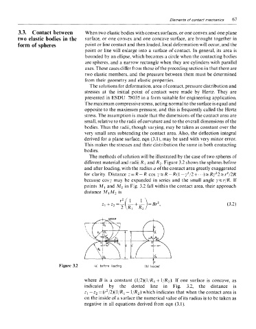
The methods of solution will be illustrated by the case of two spheres of
different material and radii R { and R 2- Figure 3.2 shows the spheres before
and after loading, with the radius a of the contact area greatly exaggerated
2
2
2
for clarity. Distance z = R-R cos y%K-R( l -y /2 + ---)vRy 2*r /2R
because cosy may be expanded in series and the small angle yzzr/R. If
points M! and M 2 in Fig. 3.2 fall within the contact area, their approach
distance M^M 2 is
Figure 3.2
where B is a constant (1/2)(1/R 1 + 1/R 2). If one surface is concave, as
indicated by the dotted line in Fig. 3.2, the distance is
r2
Zi — z 2 = ( /2)(l/K 1 — 1/-R 2) which indicates that when the contact area is
on the inside of a surface the numerical value of its radius is to be taken as
negative in all equations derived from eqn (3.1).