
Page 114 - Troubleshooting Analog Circuits
P. 114
Oscillations Do Occasionally Accompany Op Amps 101
network, as seen at the op amp’s inputs, referred to the output signal. For instance,
the p of the standard inverter configuration (Figure 8. loa) equals Z,/(Z, + Z2), so the
noise gain equals N + 1. You can raise the noise gain as shown in Figure 8. lob.
If you’re using a low-noise-gain op-amp configuration (such as a unity-gain fol-
lower that has a noise gain of 1 (Figure 8.1 la)), it’s well known that for good sta-
bility, the op amp and its feedback network can’t have appreciable unwanted phase
shift out near its unity-gain frequency. If you can increase the noise gain to 4 or 5, the
requirement for low phase shift eases considerably. No, you don’t have to change the
signal gain to 5. A noise gain of 5 or greater is easy to achieve (Figure 8.1 1 b) while
maintaining a gain of 1 for the signal. Even the unity-gain follower with a wire from
the output to the inverting input can be saved, as illustrated in Figures 8.1 IC and d.
You’ll find a more complete description of these circuits in Ref. 2, which I wrote in
1979, but meanwhile, if you are having stability problems with followers, just go
ahead and try these techniques-it’s as easy as adding a resistor box or a pot to your
existing circuit. I should also mention that some of these concepts were used by
-1
I
4 7k
7 4 + + 100 pF 5f; CL
I I
I
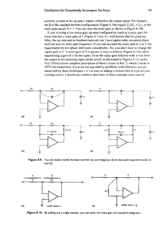
Figure 8.9. You can easily modify the basic inverter (a) and integrator (b) to decouple capacitive loads (c)
and (d).
R R
(a) I NOlSEGAIN-n+l (b)
I
Figure 8. IO. By adding just a single resistor, you can tailor the noise gain of a standard integrator.