
Page 110 - Troubleshooting Analog Circuits
P. 110
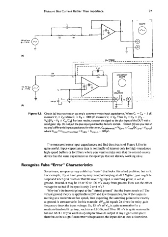
Measure Bias Current Rather Than Impedance                       97

                                                                                    *
                                                                                        SCOPE
                                                                                        0
                                                                  iiki
              (a)  l   -        h             ;           1            g        -
              ;?%E:   Tv


                                                                                                A


                               I’ve measured some input capacitances and find the circuits of Figure 8.8 to be
                             quite useful. Input-capacitance data is nominally of interest only for high-impedance
                             high-speed buffers or for filters where you want to make sure that the second-source
                             device has the same capacitance as the op amps that are already working okay.

               Recognize False “Error” Characteristics

                             Sometimes, an op amp may exhibit an “error” that looks like a bad problem. but isn’t.
                             For example, if you have your op amp’s output ramping at 4.3 V/pec, you might be
                             surprised when you discover that the inverting input, a summing point. is not at
                             ground. Instead, it may be 15 or 30 or 100 mV away from ground. How can the offset
                             voltage be so bad if the spec is only 2 or 4 mV?
                               Why isn’t the inverting input at the “virtual ground” that the books teach us? The
                             virtual ground theory is applicable at DC and low frequencies, but if the output is
                             moving at a moderate or fast speed, then expecting the summing point to be exactly
                             at ground is unreasonable. In this example, dV,,,/dt  equals 2x times the unity-gain
                             frequency times the input voltage. So, 15 mV of Vi,, is quite reasonable for a
                             medium-bandwidth op amp, such as an LF356, and 50 or 70 mV is quite reasonable
                             for an LM741. If you want an op amp to move its output at any significant speed.
                             there has to be a significant error voltage across the inputs for at least a short time.