
Page 108 - Troubleshooting Analog Circuits
P. 108
How to Do It Right.. . 95
A2
+VS
Vour
VIN Ram Rim
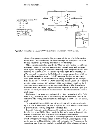
Use a minigator to select R100 a 0
Let R3 = 40 x R12
R4 = R12/20
Rl = R11
R2 = R12 Rl I
All RS Should be f 1% FUNCTION
GENERATOR
VCM = Vin x R2/(R1 + R2) (SINE OR TRIANGLE)
V,,,,, = VcM/CMRR
V,,, is related to V,,,,
Figure 8.7. Here’s how to evaluate CMRR with confidence and precision, both AC and DC.
change of the output error that is of interest, not really the p-p value before or after,
but the delta. You do not have to trim the resistor to get the slope perfect; but that is
the easy way for the guy working at his bench to see the changes.
This is a great circuit to fool around with. When you get it running, you will want
to test every op amp in your area, because it gives you such a neat high-resolution
view. It gives you a goodfeel for what is happening, rather than just hard, cold, dumb
numbers. For example, if you see a 22-mV p-p output signal that is caused by a 22-
pV error signal, you know that the CMRR really is way up near a million, which is a
lot more educational than a cold “1 19.2 dB” statement. Besides, you learn rather
quickly that the slope and the curvature of the display are important. Not all ampli-
fiers with the same “1 19.2 dB” of CMRR are actually the same, not at all. Some have
a positive slope, some may have a negative slope, and some curve madly, so that if
you took a two-point measurement, the slope would change wildly, depending on
which two points you choose. (If you increase the amplitude of the input signal, you
can also see plainly where severe distortion sets in-that’s the extent of the common-
mode range.)
Limitations: If you set the noise gain as high as 100, then this circuit will be 3 dB
down at FG~~ divided by 100, so you would only use this up to about 1 kHz on an
ordinary 1 MHz op amp, and only up to 100 Hz at a gain of 1OOO. That’s not too bad,
really.
To look at CMRR above 1 kHz, you might use RlOOc = 2 k, to give good results
up to 10 kHz. In other words, you have to engineer this circuit a little, to know where
it gives valid data. Thinking is required. Sorry about that.
For really fast work, I go to a high-speed low-gain version where R1 = R11 = 5 k,
R2 = R 12 = 5 k, and Rl00 = 2 k or 1 k or 0.5 k. This works pretty well up to 50 kHz
or more, depending on what gain-bandwidth product your amplifier has.
For best results at AC, it’s important to avoid stray capacitance of wires or of a real
switch at the points where you connect to RlOOa or R100b. Usually I get excellent
results from just grabbing on to the resistor with a minigator clip. You can avoid the
stray pf that way; if you use a good selector switch, with all the wires dressed neatly