
Page 105 - Troubleshooting Analog Circuits
P. 105
92 8. Operational Amplifiers-The Supreme Activators
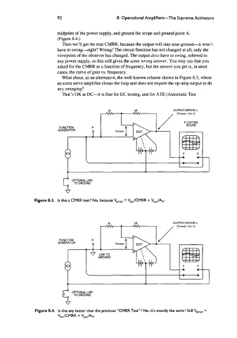
midpoint of the power supply, and ground the scope and ground point A.
(Figure 8.4.)
Then we’ll get the true CMRR, because the output will stay near ground-it won’t
have to swing-right? Wrong! The circuit function has not changed at all; only the
viewpoint of the observer has changed. The output does have to swing, referred to
any power supply, so this still gives the same wrong answer. You may say that you
asked for the CMRR as a function of frequency, but the answer you get is, in most
cases, the curve of gain vs. frequency.
What about, as an alternative, the well-known scheme shown in Figure 8.5, where
an extra servo amplifier closes the loop and does not require the op-amp output to do
any swinging?
That’s OK at DC-it is fine for DC testing, and for ATE (Automatic Test
FUNCTION
B
GENERATOR
L
OPTIONAL LINK
TO GROUND
Figure 8.3. Is this a CMRR test? No, because V,, = V,,/CMRR + Vo,JA~
OUTPUT ERROR =
(VE~) (n+l)
*
*
* LINKTO
LINKTO
GROUND
GROUND
H
V V H
t-
0
0 t-
e e - - - - - - L L
- - - -
41
41
%
A OPTIONAL LINK
Figure 8.4. Is this any better than the previous “CMRR Test”? No, it’s exactly the same! Still V,,,, =
V,,/CMRR + V,,/Av.