
Page 104 - Troubleshooting Analog Circuits
P. 104
An Uncommon Mode 91
Figure 8. I. If you run an op amp at such high impedances that
lB X R is more than 20 mV. you’ll be generating big
errors, and a V,,trim-pot can’t help you cancel
them out Please don’t even try!
--
*
,. L I I ’ ???
’
I<_,
e-. I
,
-100
VCU
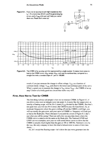
Figure 8.2. The CMRR of an op amp can’t be represented by a single number. It makes more sense to
look at the CMRR curve, Avos versus AVcM, and note its nonlinearities, compared to a
straight line with a constant slope of I part in IO0,OOO.
results if you just measure the change in offset voltage, Vos, as a function of
common-mode voltage, VCM, and observe the linear and nonlinear parts of the curve.
What’s a good way to measure the change in Vos versus VcM-the CMRR of an op
amp? I know of a really good test circuit that works very well.
First, How Not to Test for CMRR
The first thing I always tell people is how not to measure CMRR. In Figure 8.3, if
you drive a sine wave or triangle wave into point A, it seems like the output error, as
seen by a floating scope, will be (N+1) times [VcM divided by the CMRR]. But that’s
not quite true: you will see (N+1) times [the CM Errorplus the Gain Error]. So, at
moderate frequencies where the gain is rolling off and the CMRR is still high, you
will see mostly the gain error, and your curve of CMRR vs. frequency will look just
as bad as the Bode plot. That is because if you used the circuit of Figure 8.3, that’s
just what you will be seeing! There are still a few op-amp data sheets where the
CMRR curve is stated to be the same as the Bode plot. The National LF400 and
LF401 are two examples; next year we will correct those curves to show that the
CMRR is actually much higher than the gain at 100 or lo00 Hz. National is not, by
the way, the only company to have this kind of absurd error in some of their data
sheets.. . .
Ah, let’s avoid that floating scope-let’s drive the sine wave generator into the