
Page 106 - Troubleshooting Analog Circuits
P. 106
First, How Not to Test for CMRR 93
Equipment), for production test, and for stepped DC levels. And it will give the same
answer as my circuit at all low frequencies up to where it doesn’t give the same an-
swer. Now, what frequency would that be?? Nobody knows! Because if you have an
op amp with low CMRR, the servo scheme will work accurately up to one frequency,
and if you have an op amp with high CMRR, the servo scheme will work accurately
only up to a different frequency. Also, the servo amplifier adds so much gain into the
loop that ringing or overshoot or marginal stability at some mid frequencies is in-
evitable. That is much too horrible for me to worry about-I will just avoid that, by
using a circuit which gives very consistent and predictable results.
Specifically, I ran an LF356 in the circuit of Fig. 8.3, and I got an error of 4 mV p-
p at 1 kHz-a big fat quadrature error, 90 degrees out of phase with the output-see
the upper trace in Figure 8.6.
If you think that is the CM error, you might say the CMRR is as low as 5,000 at 1
kHz, and falling rapidly as the frequency increases. But the actual CMRR error is
about 0.2 mV p-p-see the lower trace of Figure. 8.6-and thus the CMRR is about
VCM
c-36 VOUT = -
II CMRR (N+l)
I’ ‘: >TOSCOPE
OR TO ATE
(h
(SINE. SOUARE, TRIANGLE)
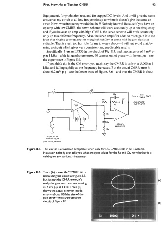
Figure 8.5. This circuit is considered acceptable when used for DC CMRR tests in ATE systems.
However, nobody ever tells you what are good values for the Rs and Cs, nor whether it is
valid up to any particular frequency.
Figure 8.6. Trace (A) shows the “CMRR error
taken using the circuit of Figure 8.3.
But it’s not the CMRR error, it’s
really the gain error you are looking
at, 4 mV p-p at I kHz. Trace (B)
shows the actual common-mode
error-about 1/20 the size of the
gain error-measured using the
circuit of Figure 8.7.