
Page 115 - Troubleshooting Analog Circuits
P. 115
I02 8. Operational Amplifiers-The Supreme Activators
10k
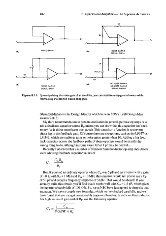
NOISE GAIN-I NOISE GAIN=6
SIGNAL GAIN-1
DC NOISE GAIN-1
NOISE GAIN-6 AC NOISE GAIN4
SIGNAL GAIN-I SIGNAL GAIN-1
Figure 8. I I. By manipulating the noise gain of an amplifier, you can stabilize unity-gain followers while
maintaining the desired closed-loop gain.
Glenn DeMichele in his Design Idea for which he won EDN’s 1988 Design Idea
award (Ref. 3).
My third recommendation to prevent oscillation in general-purpose op amps is to
add a feedback capacitor across RF unless you can show that this capacitor isn’t nec-
essary (or is doing more harm than good). This capacitor’s function is to prevent
phase lag in the feedback path. Of course there are exceptions, such as the LF357 or
LM349, which are stable at gains or noise gains greater than 10. Adding a big feed-
back capacitor across the feedback paths of these op amps would be exactly the
wrong thing to do, although in some cases 1/2 or 1 pf may be helpful ....
Recently I observed that a number of National Semiconductor op-amp data sheets
were advising feedback capacitor values of
CinRin
CF = -
RF
But, if you had an ordinary op amp whose Ci, was 5 pF and an inverter with a gain
of -0.1, with RF = 1 MQ and R,, = 10 MR, this equation would tell you to use a CF
of 50 pF and accept a frequency response of 3 kHz. That would be absurd! If you
actually build this circuit, you’ll find that it works well with CF = 1.5 pF, which gives
the inverter a bandwidth of 100 kHz. So, we at NSC have just agreed to deep-six that
equation. We have a couple new formulas, which we’ve checked carefully, and we
have found that you can get considerably improved bandwidth and excellent stability.
For high values of gain and of R,, use the following equation: