
Page 206 - Troubleshooting Analog Circuits
P. 206
C. Understanding and Reducing Noise on 3-Terminal Voltage Regulators I93
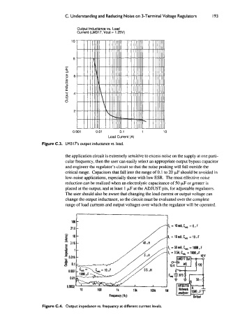
Output Inductance vs. Load
Current (LM317, Vout = 1.25V)
0.001 0.01 0.1 1 10
Load Current (A)
Figure C.3. LM3 17’s output inductance vs. load.
the application circuit is extremely sensitive to excess noise on the supply at one pani-
cular frequency, then the user can easily select an appropriate output bypass capacitor
and engineer the regulator’s circuit so that the noise peaking will fall outside the
critical range. Capacitors that fall into the range of 0.1 to 20 pF should be avoided in
low-noise applications, especially those with low ESR. The most effective noise
reduction can be realized when an electrolytic capacitance of 50 pF or greater is
placed at the output, and at least 1 pF at the ADJUST pin, for adjustable regulators.
The user should also be aware that changing the load current or output voltage can
change the output inductance, so the circuit must be evaluated over the complete
range of load currents and output voltages over which the regulator will be operated.
Figure C.4. Output impedance vs. frequency at different current levels.