
Page 207 - Troubleshooting Analog Circuits
P. 207
Appendix D
~~
Testing Fast Comparators for Voltage
Offset
As mentioned in Chapter 9, it is not trivially easy to measure the Voffset of fast
comparators, but it is possible, if you think about all the aspects of the problem. Fast
comparators all have a tendency to oscillate when their input voltage is nearly zero.
And yet to measure offset, you have to get the input voltage near zero. The solution
to this dilemma is to force the comparator to oscillate at the frequency you define.
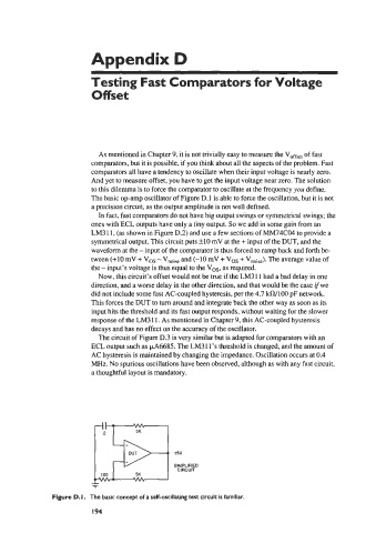
The basic op-amp oscillator of Figure D. 1 is able to force the oscillation, but it is not
a precision circuit, as the output amplitude is not well defined.
In fact, fast comparators do not have big output swings or symmetrical swings; the
ones with ECL outputs have only a tiny output. So we add in some gain from an
LM3 1 1, (as shown in Figure D.2) and use a few sections of MM74C04 to provide a
symmetrical output. This circuit puts +lo mV at the + input of the DUT, and the
waveform at the - input of the comparator is thus forced to ramp back and forth be-
tween (+lo mV + VOS - Vnoise and (-10 mV + VOS + Vnoise). The average value of
the - input’s voltage is thus equal to the VOS, as required.
Now, this circuit’s offset would not be true if the LM3 1 1 had a bad delay in one
direction, and a worse delay in the other direction, and that would be the case ifwe
did not include some fast AC-coupled hysteresis, per the 4.7 kfl/100 pF network.
This forces the DUT to turn around and integrate back the other way as soon as its
input hits the threshold and its fast output responds, without waiting for the slower
response of the LM3 1 1. As mentioned in Chapter 9, this AC-coupled hysteresis
decays and has no effect on the accuracy of the oscillator.
The circuit of Figure D.3 is very similar but is adapted for comparators with an
ECL output such as kA6685. The LM31l’s threshold is changed, and the amount of
[-a
AC hysteresis is maintained by changing the impedance. Oscillation occurs at 0.4
MHz. No spurious oscillations have been observed, although as with any fast circuit,
a thoughtful layout is mandatory.
i5v
SIMPLIFIED
CIRCUIT
100 5K
-
Figure D. I. The basic concept of a self-oscillating test circuit is familiar.
I 94