
Page 37 - Troubleshooting Analog Circuits
P. 37
24 2. Choosing the Right Equipment
+1.5V
vou, -+l nhffc
HOT JUNCTION.
CHROUEL-UUYEL
ni~twocouPLE.
TYPE K. 408 rvcC
1
-
'' 1 TEMPERATURE^ 14.55 LA
ULleRATE
4
2.35 fi 4 7.4 ,,A
2
4 m
NOTE
ALL RESISTORS f14L
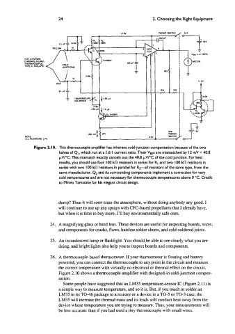
Figure 2. IO. This thermocouple amplifier has inherent cold-junction compensation because of the two
halves of Q,, which run at a I .6 I current ratio. Their VsEs are mismatched by I2 mV + 40.8
clv/.C. This mismatch exactly cancels out the 40.8 pV/OC of the cold junction. For best
results, you should use four IO0 Idn resistors in series for RI and two 100 ks1 resistors in
series with two IO0 ks1 resistors in parallel for Rz-all resistors of the same type, from the
same manufacturer. Q1 and its surrounding components implement a correction for very
cold temperatures and are not necessary for thermocouple temperatures above 0 "C. Credit
to Mineo Yamatake for his elegant circuit design.
dump? Then it will soon enter the atmosphere, without doing anybody any good. I
will continue to use up any sprays with CFC-based propellants that I already have,
but when it is time to buy more, I'll buy environmentally safe ones.
24. A magnifying glass or hand lens. These devices are useful for inspecting boards, wires,
and components for cracks, flaws, hairline solder shorts, and cold-soldered joints.
25. An incandescent lamp or flashlight. You should be able to see clearly what you are
doing, and bright lights also help you to inspect boards and components.
26. A thermocouple-based thermometer. If your thermometer is floating and battery
powered, you can connect the thermocouple to any point in the circuit and measure
the correct temperature with virtually no electrical or thermal effect on the circuit.
Figure 2.10 shows a thermocouple amplifier with designed-in cold-junction compen-
sation.
Some people have suggested that an LM35 temperature-sensor IC (Figure 2.1 1) is
a simple way to measure temperature, and so it is. But, if you touch or solder an
LM35 in its TO46 package to a resistor or a device in a TO-5 or TO-3 case, the
LM35 will increase the thermal mass and its leads will conduct heat away from the
device whose temperature you are trying to measure. Thus, your measurements will
be less accurate than if you had used a tiny thermocouple with small wires.