
Page 32 - Troubleshooting Analog Circuits
P. 32
Choosing the Right Equipment 19
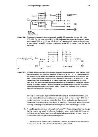
Ri SELECTOR SWITCH
SELECTOR MR MODE
1 7
1 I 0
MOTES:
15sRls10k
ISlrS%~loM
100 PFsCI ~0.22 pF
Figure 2.6. This general schematic is for a commercially available RC substitution box, the VIZ Model
a -
WC4 I2A. The unit costs around $I 39 in I99 I dollars and has resistor and capacitor values
in the range of 15 C? to 10 MC? and 100 pF to 0.2 pF, respectively. It can be configured to be
an open circuit, a series RC, resiston, capacitors, a parallel RC, or a short circuit. See text for
availability.
E-
I
I
I
l
SELECTOR
Figure 2.7. RC boxes based on these schematics extend component ranges beyond those available in off-
the-shelf versions. You can house the series RC circuit in (a) in a 1 X I X 2-inch copper-clad
box. Use the smaller plastic-film-dielectric tuning capacitors or whatever is convenient, and a
small I -turn pot. Build the circuit in (b) with tantalum or electrolytic (for values of I FF and
higher) capacitors, but remember to be careful about their polarities and how you apply
them. Also, you might consider using mylar capacitors for smaller values. Sometimes ids very
valuable to compare a mylar, a tantalum, and an aluminum electrolytic capacitor of the same
value! Use 18-position switches to select R and C values. And, stay away from wirewound
resistors; their inductance is too high.
the body of your scope. If you have trouble obtaining an isolation transformer. you
can use a pair of transformers (step-down, step-up) back-to-back (Figure 2.8). Or. if
cost isn't an issue, you can use isolated probes. These probes let you display small
signals that have common-mode voltages of hundreds of volts with respect to ground,
and they won't require you to wear insulated gloves when adjusting your scope.
10. A variable autotransformer, often called a Variacm.' This instrument lets you change
the line voltage and watch its effect on the circuit-a very useful trick. (Warning: A
variable autotransformer is not normally an isolation transformer. You may need to
cascade one of each, to get safe adjustable power.)
I. Registered TM of CENRAD Corp.. Concord, MA. Variacs can be purchased from JLM Electronics.
56 Somerset St.. P.O. Box 10317, West Hartford. CT 061 10. (203) 233-0600.