
Page 28 - Troubleshooting Analog Circuits
P. 28
Choosing the Right Equipment 15
hooks or points. Switchable 1 X/lOX probes are useful for looking at both large and
very small signals. You should be aware that 1 X probes only have a 16- or 20-MHz
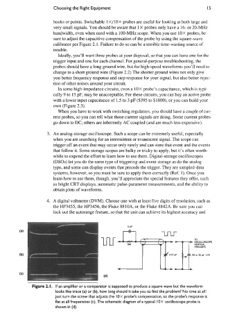
bandwidth, even when used with a 100-MHz scope. When you use 1OX probes, be
sure to adjust the capacitive compensation of the probe by using the square-wave
calibrator per Figure 2.1. Failure to do so can be a terrible time-wasting source of
trouble.
Ideally, you’ll want three probes at your disposal, so that you can have one for the
trigger input and one for each channel. For general-purpose troubleshooting, the
probes should have a long ground wire, but for high-speed waveforms you’ll need to
change to a short ground wire (Figure 2.2) The shorter ground wires not only give
you better frequency response and step response for your signal, but also better rejec-
tion of other noises around your circuit.
In some high-impedance circuits, even a 1OX probe’s capacitance, which is typi-
cally 9 to 15 pF, may be unacceptable. For these circuits, you can buy an active probe
with a lower input capacitance of 1.5 to 3 pF ($395 to $1800), or you can build your
own (Figure 2.3).
When you have to work with switching regulators, you should have a couple of cur-
rent probes, so you can tell what those current signals are doing. Some current probes
go down to DC; others are inherently AC coupled (and are much less expensive).
3. An analog-storage oscilloscope. Such a scope can be extremely useful, especially
when you are searching for an intermittent or evanescent signal. The scope can
trigger off an event that may occur only rarely and can store that event and the events
that follow it. Some storage scopes are balky or tricky to apply, but it’s often worth-
while to expend the effort to learn how to use them. Digital-storage oscilloscopes
(DSOs) let you do the same type of triggering and event storage as do the analog
type, and some can display events that precede the trigger. They are sampled-data
systems, however, so you must be sure to apply them correctly (Ref. 1). Once you
learn how to use them, though, you’ll appreciate the special features they offer, such
as bright CRT displays, automatic pulse-parameter measurements, and the ability to
obtain plots of waveforms.
4. A digital voltmeter (DVM). Choose one with at least five digits of resolution, such as
the HP3455, the HP3456, the Fluke 8810A, or the Fluke 8842A. Be sure you can
lock out the autorange feature, so that the unit can achieve its highest accuracy and
Figure 2. I. If an amplifier or a comparator is supposed to produce a square wave but the waveform
looks like trace (a) or (b), how long should it take you to find the problem? No time at all!
Just turn the screw that adjusts the I OX probe’s compensation, so the probe’s response is
flat at all frequencies (c). The schematic diagram of a typical I OX oscilloscope probe is
shown in (d).