
Page 33 - Troubleshooting Analog Circuits
P. 33
20 2. Choosing the Right Equipment
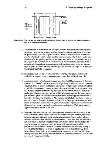
Figure 2.8. You can use this back-to-back vandormer configuration to achieve line isolation similar to
that of an isolation transformer.
11. A curve tracer. A curve tracer can show you that two transistors may have the same
saturation voltage under a given set of conditions even though the slope of one may
be quite different from the slope of the other. If one of these transistors works well
and the other badly, a curve tracer can help you understand why. A curve tracer can
also be useful for spotting nonlinear resistances and conductances in diodes, capaci-
tors, light bulbs, and resistors. A curve tracer can test a battery by loading it down or
recharging it. It can check semiconductors for breakdown. And, when you buy the
right adapters or cobble them up yourself, you can evaluate the shape of the gain, the
CMRR, and the PSRR of op amps.
12. Spare repair parts for the circuit-under-test. You should have these parts readily
available, so you can swap components to make sure they still work correctly.
13. A complete supply of resistors and capacitors. You should have resistors in the range
from 0.1 R to 100 MR and capacitors from 10 pF to 1 pF. Also, 10,100, and lo00 pF
capacitors come in handy. Just because your circuit design doesn’t include a 0.1 R or
a 100 MR resistor doesn’t mean that these values won’t be helpful in troubleshooting
it. Similarly, you may not have a big capacitor in your circuit; but, if the circuit sud-
denly stops misbehaving when you put a 3800 pF capacitor across the power supply,
you’ve seen a quick and dramatic demonstration that power-supply wobbles have a
lot to do with the circuit’s problems. Also, several feet of plastic-insulated solid wire
(telephone wire) often come in handy. A few inches of this type of twisted-pair wire
makes an excellent variable capacitor, sometimes called a “gimmick.” Gimmicks are
cheap and easy to vary by simply winding or unwinding them. Their capacitance is
approximately one picofarad per inch.
14. Schematic diagrams. It’s a good idea to have several copies of the schematic of the
circuit-under-test. Mark up one copy with the normal voltages, currents, and wave-
forms to serve as a reference point. Use the others to record notes and waveform
sketches that relate to the specific circuit-under-test. You’ll also need a schematic of
any homemade test circuit you plan to use. Sometimes, measurements made with
your homemade test equipment may not agree with measurements made by
purchased test equipment. The results from each tester may not really be “wrong”:
They might differ because of some design feature, such as signal filtering. If you
have all the schematics for your test equipment, you can more easily explain these
incompatibilities. And, finally, the data sheets and schematics of any ICs used in your
circuit will also come in handy.