
Page 29 - Troubleshooting Analog Circuits
P. 29
16 2. Choosing the Right Equipment
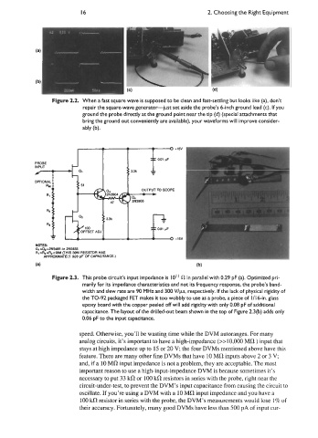
Figure 2.2. When a fast square wave is supposed to be clean and fast-settling but looks like (a), don’t
repair the square-wave generator-just set aside the probe’s 6-inch ground lead (c). If you
ground the probe directly at the ground point near the tip (d) (special attachments that
bring the ground out conveniently are available), your waveforms will improve consider-
ably (b).
OFFSET ADJ
-15v
NQIES:
a, =&-2N5486 or 2N5485
RI=R~-R~=~OM (THIS 3oM RESISTOR HAS
APPROXIMAELY 0.08 pF OF CAPACITANCE.)
(a) (b)
Figure 2.3. This probe circuit’s input impedance is IO’ fl in parallel with 0.29 pF (a). Optimized pri-
marily for its impedance characteristics and not its frequency response, the probe’s band-
width and slew rate are 90 MHz and 300 Wps, respectively. If the lack of physical rigidity of
the TO-92 packaged FET makes it too wobbly to use as a probe, a piece of 1/16-in. glass
epoxy board with the copper peeled off will add rigidity with only 0.08 pF of additional
capacitance. The layout of the drilled-out beam shown in the top of Figure 2.3(b) adds only
0.06 pF to the input capacitance.
speed. Otherwise, you’ll be wasting time while the DVM autoranges. For many
analog circuits, it’s important to have a high-impedance (>>10,000 Mfl ) input that
stays at high impedance up to 15 or 20 V; the four DVMs mentioned above have this
feature. There are many other fine DVMs that have 10 MR inputs above 2 or 3 V;
and, if a 10 Mfl input impedance is not a problem, they are acceptable. The most
important reason to use a high-input-impedance DVM is because sometimes it’s
necessary to put 33 kfl or 100 kR resistors in series with the probe, right near the
circuit-under-test, to prevent the DVM’s input capacitance from causing the circuit to
oscillate. If you’re using a DVM with a 10 Mfl input impedance and you have a
100 kfl resistor in series with the probe, the DVM’s measurements would lose 1 % of
their accuracy. Fortunately, many good DVMs have less than 500 pA of input cur-