
Page 30 - Troubleshooting Analog Circuits
P. 30
Choosing the Right Equipment 17
CIRCUIT -- HI
10Kor l00K
UNDER __ 0.001 9 1-
-- orO.O1
TEST 1 K or 10K or lOOK or 0.1 ’? Lo DVM
t- - ~
0.01 or 0.1
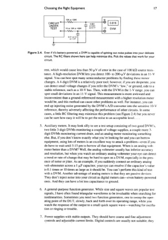
Figure 2.4. Even if it’s battery-powered, a DVM is capable of Spitting out noise pulses into your delicate
circuit. The RC filters shown here can help minimize this. Pick the values that work for your
circuit.
rent, which would cause less than 50 pV of error in the case of 100 kR source resis-
tance. A high-resolution DVM lets you detect 100- to 200-pV deviations in an 1 I -V
signal. You can best spot many semiconductor problems by finding these minor
changes. A 4-digit DVM is a relatively poor tool; however, if you are desperate. you
can detect small voltage changes if you refer the DVM’s “low,” or ground, side to a
stable reference, such as a 10-V bus. Then, with the DVM in the I-V range, you can
spot small deviations in an 1 1-V signal. This measurement is more awkward and
inconvenient than a ground-referenced measurement with a higher resolution meter
would be, and this method can cause other problems as well. For instance, you can
end up injecting noise generated by the DVM’s A/D converter into the sensitive IO-V
reference, thereby adversely affecting the performance of other circuits. In some
cases, a little RC filtering may minimize this problem (see Figure 2.4) but you never
can be sure how easy it will be to get the noise to an acceptable level. . . .
5. Auxiliary meters. It may look silly to see a test setup consisting of two good DVM’s,
two little 3-digit DVMs monitoring a couple of voltage supplies. a couple more 3-
digit DVMs monitoring current drain, and an analog meter monitoring something
else. But, if you don’t know exactly what you’re looking for and you can borrow
equipment, using lots of meters is an excellent way to attack a problem-even if you
do have to wait until 5: 15 pm to borrow all that equipment. When is an analog volt-
meter better than a DVM? Well, the analog voltmeter usually has inferior accuracy
and resolution, but when you watch an ordinary analog voltmeter your eye can detect
a trend or rate-of-change that may be hard to spot on a DVM, especially in the pres-
ence of noise or jitter. As an example, if you suddenly connect an ordinary analog
volt-ohmmeter across a 1 p,F capacitor, your eye can resolve if the capacitor’s value
is 0.1 times or 10 times as large as it should be. You can’t perform this kind of test
with a DVM. Another advantage of analog meters is that they are passive devices:
They don’t inject noise into your circuit as digital meters can--even battery-powered
ones. And they can have a lot less capacitance to ground.
6. A general-purpose function generator. While sine and square waves are popular test
signals, I have often found triangular waveforms to be invaluable when searching for
nonlinearities. Sometimes you need two function generators, one to sweep the oper-
ating point of the DUT, slowly, back and forth over its operating range, while you
watch the response of the output to a small quick square wave-watching for oscilla-
tion or ringing or trouble.
7. Power supplies with stable outputs. They should have coarse and fine adjustment
controls and adjustable current limits. Digital controls are usually not suitable; they