
Page 66 - Troubleshooting Analog Circuits
P. 66
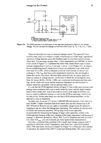
Leakage Can Be a Problem                                          53


                                                                 DIGITAL VOLTMETER
                             LOW-
                             NOISE
                              ”S
                            (VARIABLE)


                                                                *
                                                                 I
                                 NOTES:
                                 St -RESISlOR  SENSE SELECTOR
                                 RI-DVM  INPUT IMPEDANCE. FOR  SOME WMS, RI IS (OM
                                  IN SOME MNGES (CONSULT USERS MANUAL)
                  Figure 5.3.  The DVM approach is an alternative to the approach illustrated in Figure 5. I  for testing
                            leakage.  You can calculate the leakage current from Ohm’s Law: Vs = I,  X  Rs, or IL = V,/R,.


                              There are basically two ways to measure leakage current. The approach I have
                            used for many years is to connect a couple of transistors as a wide-range. logarithmic,
                            current-to-voltage detector across the feedback path of a low-bias-current op amp.
                            These days, I’m not using vacuum tubes-I   have graduated to an LMC660, as shown
                            in the circuit of Figure 5.1. I calibrated the meter with a hand-drawn scale to sense
                            currents ranging from +1 pA to +1 mA and -1  pA to -1  mA (Figure 5.2). As long as
                            the air conditioning doesn’t break down, I know my calibration won’t drift much
                            more than 10 or 20%, which is adequate to tell me which decade of current I am
                            working in. (The V,,  does have some temperature sensitivity, but not enough to
                            bother this circuit very much.) Because these transistors are, of course, quite non-
                            linear as current-to-voltage sensors, you do have to shield the summingpoint away
                            from AC noises (60 Hz, 120 Hz, 1 MHz. etc.) to prevent rectification and false read-
                            ings. So the whole test circuit and the unknown impedance are best located in a
                            shallow metal box, grounded, with an optional metal cover.
                              It’s true that the DVM approach shown in Figure 5.3 has a little more accuracy and
                            perhaps more resolution; but it too is easily fooled by noise, and the digital readout
                            doesn’t show trends well. And, if you want to cover a wide range of currents, you
                            have to switch in different resistors or wait for the DVM to autorange, which is not
                            my idea of fun. On the other hand, you can find a DVM almost anywhere, so this
                            approach is easy to implement.
                              In either case, if you put 15 V across 1,OOO,OOO MO and measure 15 PA, that is at
                            least 50,000 X higher resolution than most meters that can only measure up to 20
                            Ma. Whichever detector you use, apply a reasonable voltage across the unknown
                            impedance and see where the leakage gets interesting. This method can also be used
                            for diodes and transistor junctions. The op-amp circuit is not especially
                            recommended for measuring the leakage of large-value capacitors; neither is the
                            DVM approach because of the slow charging of the large capacitance, and because of
                            soakage,  or dielectric absorption, effects. But, if you’re desperate and start out with a
                            low value of R,,,,,   you can eventually get some approximate measurements.
                              Recently, a customer had a problem with a simple basic design using an LM3 17
                            regulator in which the circuit’s impedances were fairly low-just  a few hundred
                            ohms. (The same basic circuit as in chapter 14, Figure 14.3.) After just a few minutes
                            of operation, the output of the LM3 17 would start drifting badly. The cause turned