
Page 200 - Tunable Lasers Handbook
P. 200
178 F. J. Duarte
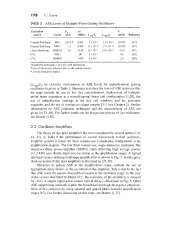
TABLE 5 ASE Levels of Multiple-Prism Grating Oscillatorsa
Excitation Eo A\! C
source Cavity (mJ) (I\IHz) ZiSE /Zf pisE/pf (mM) Reference
Coaxial flashlamp MPL 2.61.2 1360 7 x 10⁻⁹ 1.2 x 10⁻⁹ 0.0125 [47]
Coaxial flashlamp MPLh -3 1360 6 x 10⁻¹⁰ 1.7 x 10⁻¹⁰ 0.0125 [47]
Linear flashlamp HMPGI 3.6 5138 6 x 10-11 2.9 x 10⁻¹' -0.01 [17]
CVL MPL. 60 ZX 10-7 0.6 [181
CVL HMPGI -400 5 x 10' 2.0 ~491
OAdapted from Duane et al. [47], with permission.
buses of intracavity polarizer next to the output coupler.
cUses an intracavitp etalon.
(pASE/pI) by (AA/Ah). Information on ASE levels for multiple-prism grating
oscillators is given in Table 5. Measures to reduce the level of ASE at the oscilla-
tor stage include the use of low dye concentrations, deployment of multiple-
prism beam expanders in a nonorthogonal beam exit configuration [ 1.501, the
use of antireflection coatings at the dye cell windows and the prismatic
expander, and the use of a polarizer output coupler [51] (see Chapter 2). Further
information on ASE reduction techniques and the measurement of ASE are
given in [52-581. For further details on the design and physics of dye oscillators,
see Duarte [1,50].
2.3 Oscillator-Amplifiers
The theory of dye laser amplifiers has been considered by several authors [ 10,
14, 211. In Table 6 the performance of several transversely excited oscillator-
amplifier systems is listed. All these systems use a single-pass configuration at the
amplification stage(s). The first three systems use single-transverse excitation. The
master-oscillator power-amplifier (MOPA) chain delivering high average powers
(>I .3 kW) uses double-transverse excitation at the amplification stages. A typical
dye laser system utilizing multistage amplification is shown in Fig. 5. Semilongitu-
dinal excitation of dye laser amplifiers is discussed by [21,39].
Measures to reduce ASE at the amplification stages include the use of
appropriate delay factors in the excitation of the amplifier. This is due to the fact
that ASE leads the narrow-linewidth emission at the oscillator stage. In the case
of the system described by Dupre [61], the excitation of the amplifiers is delayed
by -9 ns. A simple approach to induce optical delay is illustrated in Fig. 5. Other
ASE suppression methods exploit the broadband and high-divergence character-
istics of this emission by using spectral and spatial filters between amplification
stages [63]. For further discussion on this topic. see Duarte [1,37].