
Page 202 - Tunable Lasers Handbook
P. 202
180 F. J. Duarte
FIGURE 5 Dye laser system illustrating multistage amplification. AC, amplifier cell; BS, beam-
splitter; BSO, beam-shaping optics; F, spectral filter; M, mirror. (Reprinted with permission from
Duarte and Foster [62].)
fluid
-Coding Coding fluid
k*T>Reflector Flashlamp
Flashlamp
Reflector
n
Dye cell
Dye active
region '\-/ 0
Dye Ftive
region
Dye cel I
b
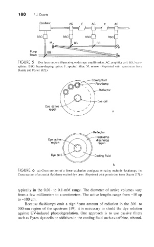
FIGURE 6 (a) cross section of a linear excitation configuration using multiple flashlamps. (b)
Cross section of a coaxial flashlamp excited dye laser. (Reprinted with permission from Duarte [37].)
typically in the 0.01- to 0.1-mM range. The diameter of active volumes vary
from a few millimeters to a centimeters. The active lengths range from -10 up
to -100 cm.
Because flashlamps emit a significant amount of radiation in the 200- to
300-nm region of the spectrum [19], it is necessary to shield the dye solution
against UV-induced photodegradation. One approach is to use passive filters
such as Pyrex dye cells or additives in the cooling fluid such as caffeine, ethanol,