
Page 484 - Tunable Lasers Handbook
P. 484
444 Stephen Vincent Benson
t
cavity
mirror
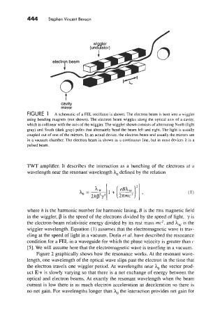
FIGURE 1 A schematic of a FJ% oscillator is shown. The electron beam is bent into a wiggler
using bending magnets (not shown). The electron beam wiggles along the optical axis of a cavity,
which is collinear with the axis of the wiggler. The wiggler shown consists of alternating North (light
gray) and South (dark gray) poles that alternately bend the beam left and right. The light is usually
coupled out of one of the mirrors. In an actual device, the electron beam and usually the mirrors are
in a vacuum chamber. The electron beam is shown as a continuous line, but in most devices it IS a
pulsed beam.
TWT amplifier. It describes the interaction as a bunching of the electrons at a
wavelength near the resonant wavelength h, defined by the relation
eBh
where h is the harmonic number for harmonic lasing, B is the rms magnetic field
in the wiggler, is the speed of the electrons divided by the speed of light, y is
the electron-beam relativistic energy divided by its rest mass mc2, and h, is the
wiggler wavelength. Equation (1) assumes that the electromagnetic wave is trav-
eling at the speed of light in a vacuum. Doria et al. have described the resonance
condition for a FEL in a waveguide for which the phase velocity is greater than c
[SI. We will assume here that the electromagnetic wave is traveling in a vacuum.
Figure 2 graphically shows how the resonance works. At the resonant wave-
length, one wavelength of the optical wave slips past the electron in the time that
the electron travels one wiggler period. At wavelengths near h, the vector prod-
uct ET is slowly varying so that there is a net exchange of energy between the
optical and electron beams. At exactly the resonant wavelength when the beam
current is low there is as much electron acceleration as deceleration so there is
no net gain. For wavelengths longer than h, the interaction provides net gain for