
Page 485 - Tunable Lasers Handbook
P. 485
9 Tunable Free-Electron Lasers 445
1 *
Wi gler 0 0 0
B &Id a I f I
electron
trajectory
by I I
Optical I I
I
(Ex) +
E Field A I 1 2 c
\J/ \J/
-1
I
I I
I I I
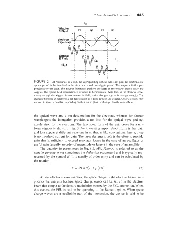
FIGURE 2 At resonance in a FEL the copropagating optical field slips past the electrons one
optical period in the time it takes the electron to travel one wiggler period. The magnetic field is per-
pendicular to the page. The electron horizontal position oscillates as the electron travels down the
miggler. The optical field polarization is assumed to be horizontal. Note that. as the electron shown
moves through the wiggler. it sees an electric field, which changes sign as it changes velocity. The
electron therefore experiences a net deceleration as it goes through the wiggler. Otier electrons may
see acceleration or no effect depending on their initial phase with respect to the optical beam.
the optical wave and a net deceleration for the electrons. whereas for shorter
wavelengths the interaction provides a net loss for the optical ~ave and ne1
acceleration for the electrons. The functional form of the gain curve for a uni-
form wiggler is shown in Fig. 3. An interesting aspect about FELs is that gain
and loss appear at different wavelengths so that. unlike conventional lasers, there
is no threshold current for gain. The laser designer’s task is therefore to provide
gain that is sufficient to exceed resonator losses in the case of an oscillator or
useful gain (usually an order of magnitude or larger) in the case of an amplifier.
The quantity in parentheses in Eq. (1). eB4,./3.rm7c2. is referred to as the
wqgler parameter (or sometimes the dejection parameter) and is typically rep-
resented by the symbol K. It is usually of order unity and can be calculated by
the relation
K = 0.931B(T)h, (cm) . (2.
At low electron-beam energies. the space charge in the electron beam corn-
plicates the analysis because space charge waves can be set up in the electron
beam that couple to the density modulation caused by the FEL interaction. When
this occurs, the FEL is said to be operating in the Raman regime. When space
charge naves are a negligible part of the interaction. the device is said to be