
Page 67 - Tunable Lasers Handbook
P. 67
48 R. C. Sze and D. G. Harris
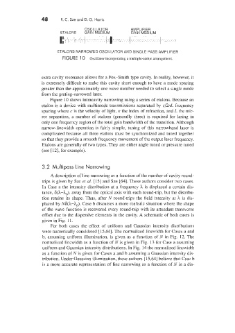
OSC I LLATOR AMPLIFIER
ETALONS GAIN MEDIUM GAIN MEDIUM
ETALONS NARROWED OSCILLATOR AND SINGLE PASS AMPLIFIER
FlGU RE 1 0 Oscillator incorporating a multiple-etalon arrangement.
extra cavity resonance allows for a Fox-Smith type cavity. In reality, however, it
is extremely difficult to make this cavity short enough to have a mode spacing
greater than the approximately one wave number needed to select a single mode
from the grating-narrowed laser.
Figure 10 shows intracavity narrowing using a series of etalons. Because an
etalon is a device with multimode transmissions separated by c/2nL frequency
spacing where c is the velocity of light, n the index of refraction, and L the mir-
ror separation, a number of etalons (generally three) is required for lasing in
only one frequency region of the total gain bandwidth of the transition. Although
narrow-linewidth operation is fairly simple, tuning of this narrowband laser is
complicated because all three etalons must be synchronized and tuned together
so that they provide a smooth frequency movement of the output laser frequency.
Etalons are generally of two types. They are either angle tuned or pressure tuned
(see [12], for example).
3.2 Multipass Line Narrowing
A description of line narrowing as a function of the number of cavity round-
trips is given by Sze et al. [15] and Sze [64]. These authors consider two cases.
In Case a the intensity distribution at a frequency h is displaced a certain dis-
tance, 6(3L-ho), away from the optical axis with each round-trip, but the distribu-
tion retains its shape. Thus, after N round-trips the field intensity at 1 is dis-
placed by N6(3L-ho). Case b discusses a more realistic situation where the shape
of the wave function is recovered every round-trip with its attendant transverse
offset due to the dispersive elements in the cavity. A schematic of both cases is
given in Fig. 1 1.
For both cases the effect of uniform and Gaussian intensity distributions
were numerically considered [15,64]. The normalized linewidth for Cases a and
b, assuming uniform illumination, is given as a function of N in Fig. 12. The
normalized linewidth as a function of N is given in Fig. 13 for Case a assuming
uniform and Gaussian intensity distributions. In Fig. 14 the normalized linewidth
as a function of N is given for Cases a and b assuming a Gaussian intensity dis-
tribution. Under Gaussian illumination, these authors [ 15,641 believe that Case b
is a more accurate representation of line narrowing as a function of N in a dis-