
Page 65 - Tunable Lasers Handbook
P. 65
46 R. C. Sze and D. G. Harris
I
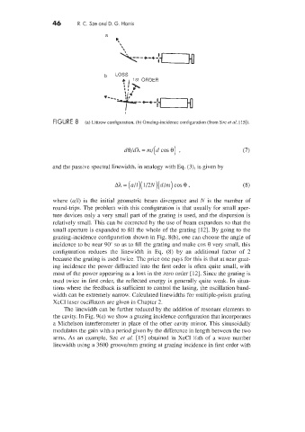
FIGURE 8 (a) Littrow configuration. (b) Grazing-incidence configuration (from Sze et al. [15]).
d0/dh = m/(d COS 0) , (7)
and the passive spectral linewidth, in analogy with Eq. (3), is given by
Ah = (./E)( 1/2N)(d/m) cos 8 , (8)
where (a/l) is the initial geometric beam divergence and N is the number of
round-trips. The problem with this configuration is that usually for small aper-
ture devices only a very small part of the grating is used, and the dispersion is
relatively small. This can be corrected by the use of beam expanders so that the
small aperture is expanded to fill the whole of the grating [12]. By going to the
grazing-incidence configuration shown in Fig. 8(b), one can choose the angle of
incidence to be near 90" so as to fill the grating and make cos 8 very small, this
configuration reduces the linewidth in Eq. (8) by an additional factor of 2
because the grating is used twice. The price one pays for this is that at near graz-
ing incidence the power diffracted into the first order is often quite small, with
most of the power appearing as a loss in the zero order [12]. Since the grating is
used twice in first order, the reflected energy is generally quite weak. In situa-
tions where the feedback is sufficient to control the lasing, the oscillation band-
width can be extremely narrow. Calculated linewidths for multiple-prism grating
XeCl laser oscillators are given in Chapter 2.
The linewidth can be further reduced by the addition of resonant elements to
the cavity. In Fig. 9(a) we show a grazing incidence configuration that incorporates
a Michelson interferometer in place of the other cavity mirror. This sinusoidally
modulates the gain with a period given by the difference in length between the two
arms. As an example, Sze et al. [15] obtained in XeCl %oth of a wave number
linewidth using a 3600 groove/mm grating at grazing incidence in first order with