
Page 64 - Tunable Lasers Handbook
P. 64
3 Tunable Excimer Laser 45
CAVITY ROUND-TRIPS CAVITY ROUND-TRIPS
Q b
FIGURE 6 (a) Beam divergence as a function of cavity roundtrips (N). (b) Curves in part (a)
corrected to go to the diffraction limit (from Sze et al. [15]).
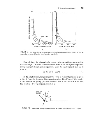
Figure 7 shows the schematic of a grating giving the incidence angle and the
diffracted angle. The order of the diffracted beam m and its angle is dependent
on the distance between groove separations d and the wavelength of light and is
given by
sin 8 + sin 8‘ = mhJd . (6)
In the simplest form, the grating can be set up in two configurations as given
in Fig. 8. Figure 8a shows the Littrow configuration. The diffracted light usually
in first order of the grating (m = 1) is reflected back in the direction of the inci-
dent beam (8 = e’). The angular dispersion is
ZEROTH I
/
FIGURE 7 Diffraction grating diagram showing incidence (e) and diffraction (e’) angles.