
Page 75 - Tunable Lasers Handbook
P. 75
56 R. C. Sze and D. G. Harris
and Pacala [74]. This involves careful implementation of a racetrack magnetic
core of met-glass materials.
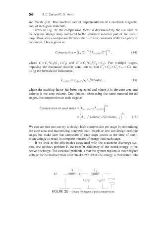
Refer to Fig. 20; the compression factor is determined by the rise time of
the original storage loop compared to the saturated inductor part of the circuit
loop. Thus, it is a comparison between the L-C time constants of the two parts of
the circuit. This is given as
'I
Compression = (L, IC) 'I2i[L pAT.)lC , (14)
where C = C1*C2/(C1 + C,) and C' = C2*C3/(C2 + C,). For multiple stages,
imposing the resonance transfer condition so that C, = C, = C, = ... = Cn and
using the formula for inductance,
where the stacking factor has been neglected and where A is the core area and
volume is the core volume. One obtains, when using the same material for all
stages, the compression at each stage as
Compression at each stage =
= [An- volume,lA~volume,,~ I )I" . (16)
We can see that one can try to design high compression per stage by minimizing
the core area and maximizing magnetic path length or one can design multiple
stages but make sure that saturation of each stage occurs at the time of maxi-
mum voltage to result in complete transfer of energy into each stage.
If we look at the efficiencies associated with the avalanche discharge sys-
tem, one obvious problem is the transfer efficiency of the stored energy to the
active discharge. The essential problem is that the system requires a much higher
voltage for breakdown than after breakdown when the energy is transferred into
I, p
FIGURE 20 Circuit for magnetic pulse compression.