
Page 77 - Tunable Lasers Handbook
P. 77
58 R. C. Sze and D. G. Harris
Additional benefits noted in these studies were order of magnitude increased
pulse repetition frequency [8 11 for a given gas flow and improved pulse-to-pulse
energy variations [82] when compared with unstabilized electrodes. One of the
most important aspects of this technology is that it allows for very simple pulse
power circuits that tend to result in compactness in design and cost effectiveness
in construction. Recently Franceschini et al. [83] have shown that some of the
stability of the inductively stabilized circuit is really due to the small peaking
capacitor, which allows for high-frequency modulation of the current. They have
obtained long lasing pulses in XeCl using the same circuit but eliminating the
inductive stabilization electrode. However, we believe it is still necessary to have
such an electrode in order to obtain long lasing pulses in the more unstable gas
mixtures of the fluorine-based excimer molecules.
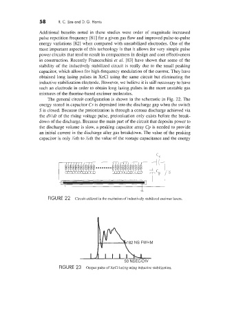
The general circuit configuration is shown in the schematic in Fig. 22. The
energy stored in capacitor Cs is deposited into the discharge gap when the switch
S is closed. Because the preionization is through a corona discharge achieved via
the dVldt of the rising voltage pulse, preionization only exists before the break-
down of the discharge. Because the main part of the circuit that deposits power to
the discharge volume is slow, a peaking capacitor array Cp is needed to provide
an initial current in the discharge after gas breakdown. The value of the peaking
capacitor is only %oth to %oth the value of the storage capacitance and the energy
I
-
FIGURE 22 Circuit utilized in the excitation of inductively stabilized excimer lasers.
FIGURE 23 Output pulse of XeCl lasing using inductive stabilization.