
Page 130 - Understanding Automotive Electronics
P. 130
2735 | CH 4 Page 117 Tuesday, March 10, 1998 11:06 AM
MICROCOMPUTER INSTRUMENTATION AND CONTROL 4
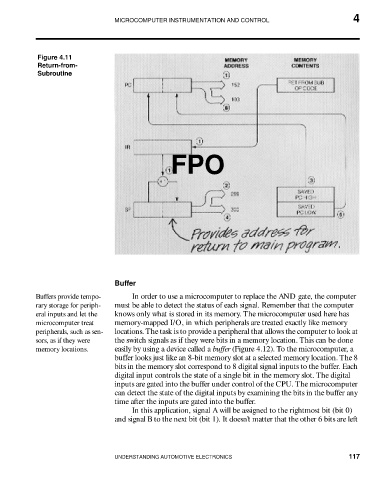
Figure 4.11
Return-from-
Subroutine
FPO
Buffer
Buffers provide tempo- In order to use a microcomputer to replace the AND gate, the computer
rary storage for periph- must be able to detect the status of each signal. Remember that the computer
eral inputs and let the knows only what is stored in its memory. The microcomputer used here has
microcomputer treat memory-mapped I/O, in which peripherals are treated exactly like memory
peripherals, such as sen- locations. The task is to provide a peripheral that allows the computer to look at
sors, as if they were the switch signals as if they were bits in a memory location. This can be done
memory locations. easily by using a device called a buffer (Figure 4.12). To the microcomputer, a
buffer looks just like an 8-bit memory slot at a selected memory location. The 8
bits in the memory slot correspond to 8 digital signal inputs to the buffer. Each
digital input controls the state of a single bit in the memory slot. The digital
inputs are gated into the buffer under control of the CPU. The microcomputer
can detect the state of the digital inputs by examining the bits in the buffer any
time after the inputs are gated into the buffer.
In this application, signal A will be assigned to the rightmost bit (bit 0)
and signal B to the next bit (bit 1). It doesn’t matter that the other 6 bits are left
UNDERSTANDING AUTOMOTIVE ELECTRONICS 117