
Page 134 - Understanding Automotive Electronics
P. 134
2735 | CH 4 Page 121 Tuesday, March 10, 1998 11:06 AM
MICROCOMPUTER INSTRUMENTATION AND CONTROL 4
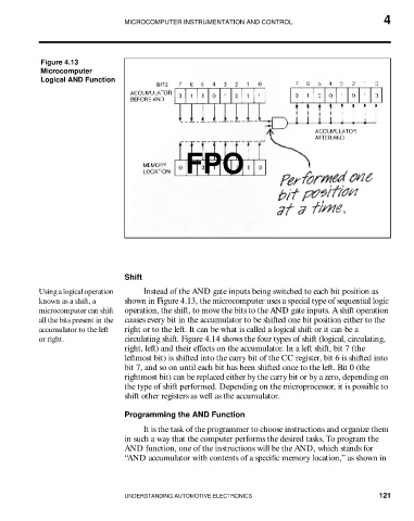
Figure 4.13
Microcomputer
Logical AND Function
FPO
Shift
Using a logical operation Instead of the AND gate inputs being switched to each bit position as
known as a shift, a shown in Figure 4.13, the microcomputer uses a special type of sequential logic
microcomputer can shift operation, the shift, to move the bits to the AND gate inputs. A shift operation
all the bits present in the causes every bit in the accumulator to be shifted one bit position either to the
accumulator to the left right or to the left. It can be what is called a logical shift or it can be a
or right. circulating shift. Figure 4.14 shows the four types of shift (logical, circulating,
right, left) and their effects on the accumulator. In a left shift, bit 7 (the
leftmost bit) is shifted into the carry bit of the CC register, bit 6 is shifted into
bit 7, and so on until each bit has been shifted once to the left. Bit 0 (the
rightmost bit) can be replaced either by the carry bit or by a zero, depending on
the type of shift performed. Depending on the microprocessor, it is possible to
shift other registers as well as the accumulator.
Programming the AND Function
It is the task of the programmer to choose instructions and organize them
in such a way that the computer performs the desired tasks. To program the
AND function, one of the instructions will be the AND, which stands for
“AND accumulator with contents of a specific memory location,” as shown in
UNDERSTANDING AUTOMOTIVE ELECTRONICS 121